Aftermarket 4x4 Parts and Accessories
Expedition & Overland Preparation
Outdoor, Camping & Bushcraft Products


Categories D2 Clock Build[3]
D2 Clock Build[3]
Building your Fourby Multifunction Clock kit.
Your Fourby Multifunction USB clock is 3D printed, we will need to do some clean up of the print before we can assemble the electronics.
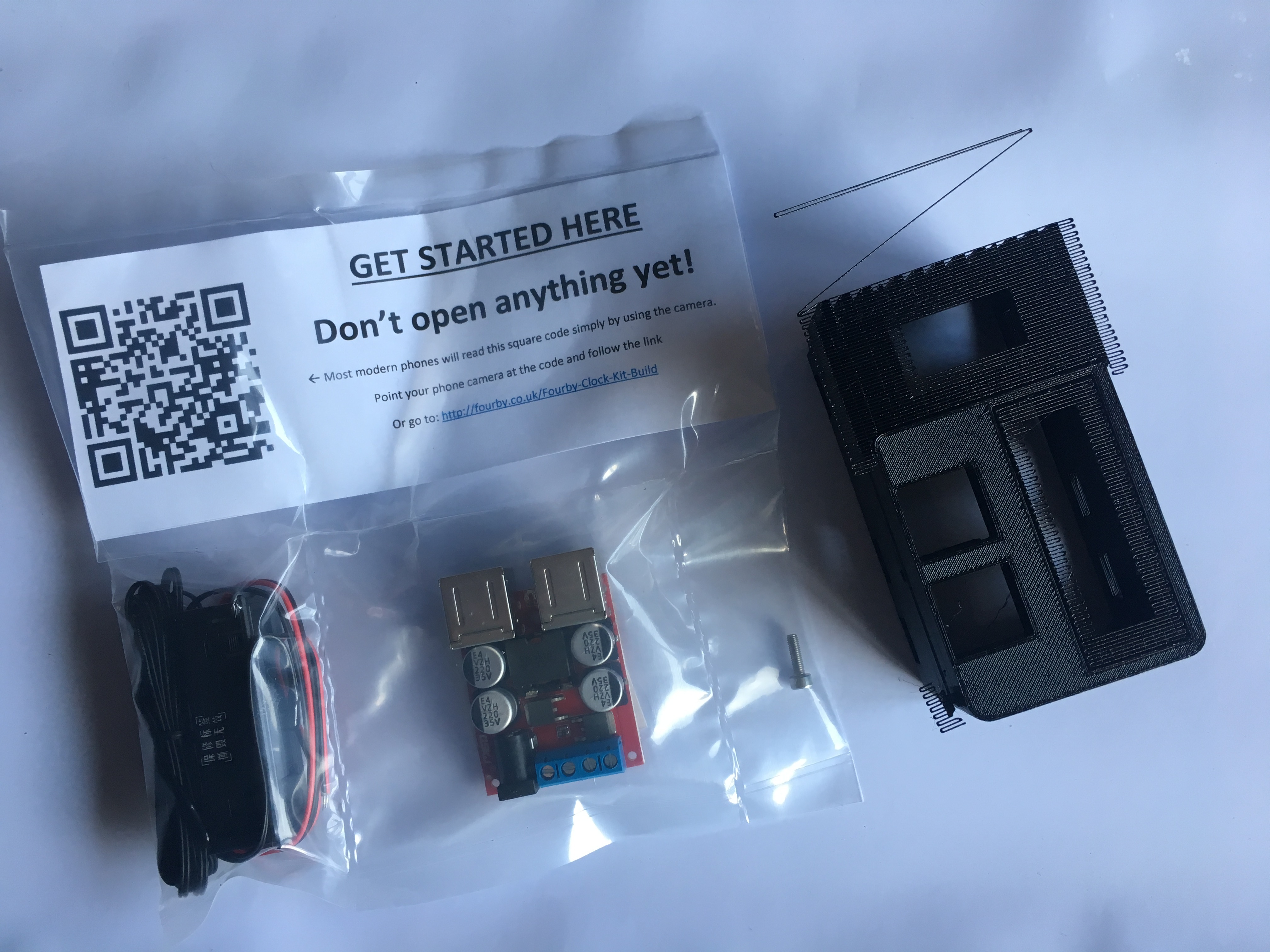
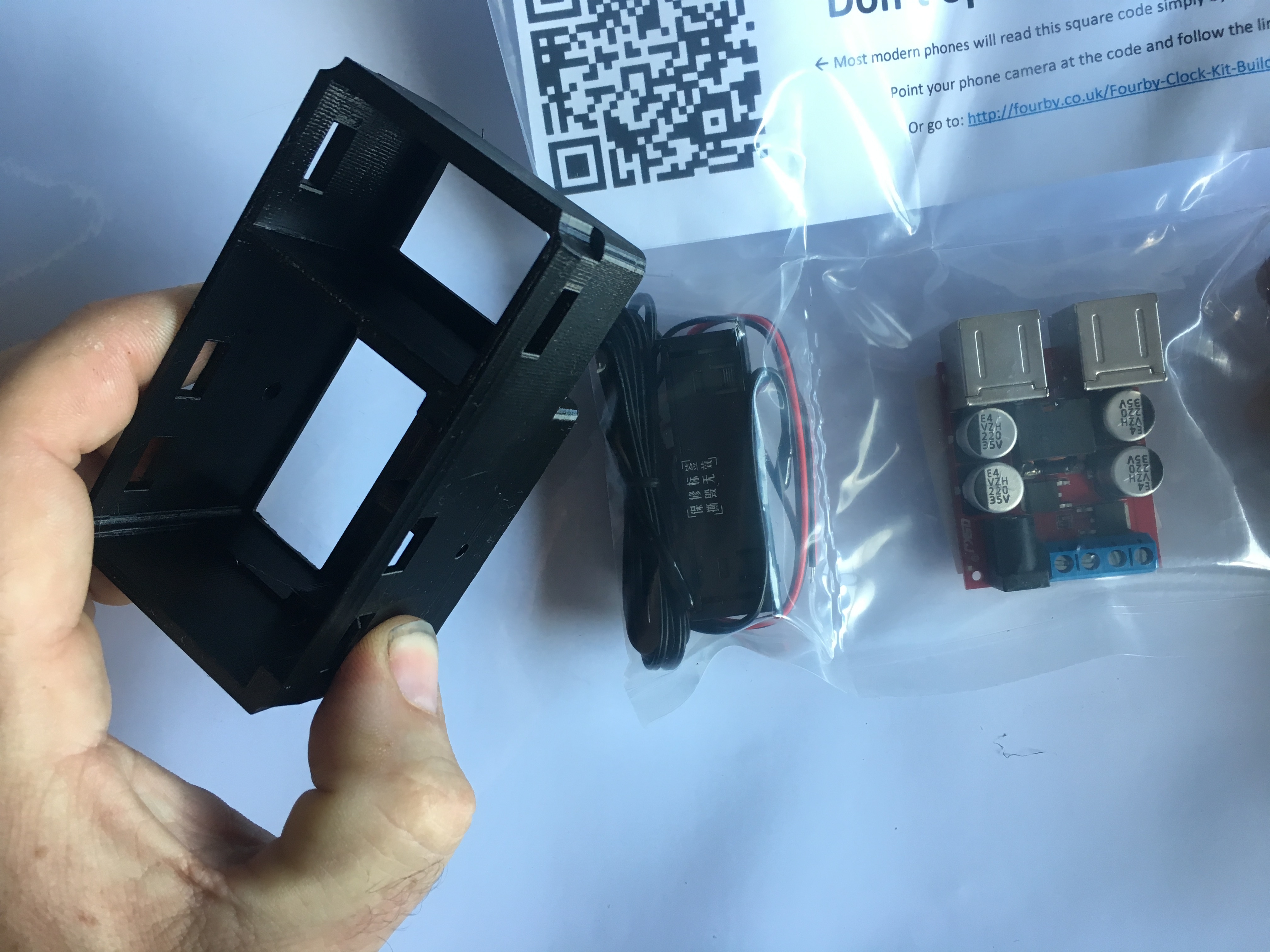
Please check the contents of your parts bag for:
- USB module
- Clock Module
- Retaining Screw
- QR code Sticker
You will need the following tools to complete your Fourby USB Clock kit build
- Wire Cutters/Strippers
- 2.5mm Allen Key
- Small Connection Flat Blade screwdriver
- A ruler or tape measure
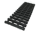
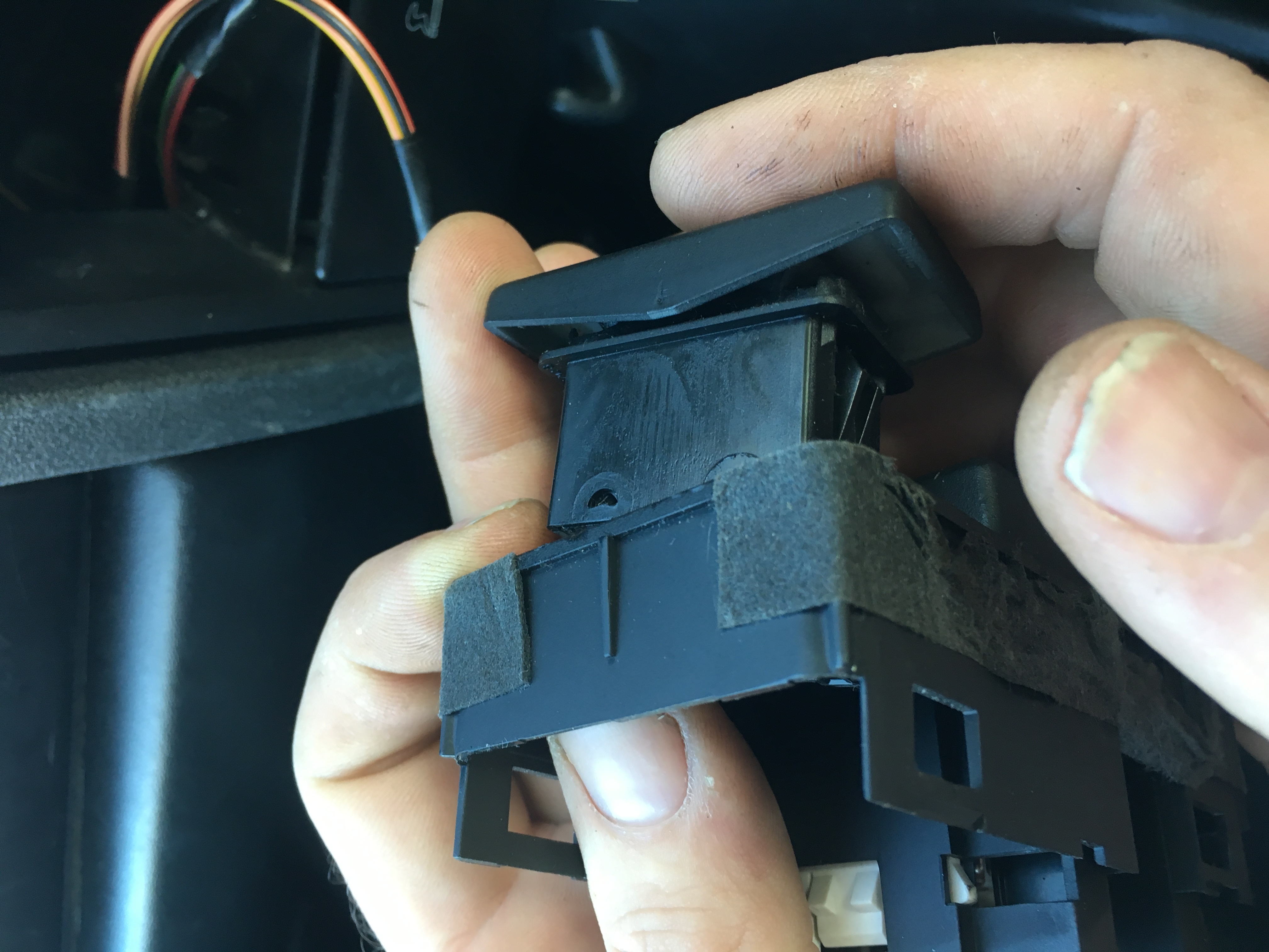
Follow the pictures below to remove the support material created during the printing phase.
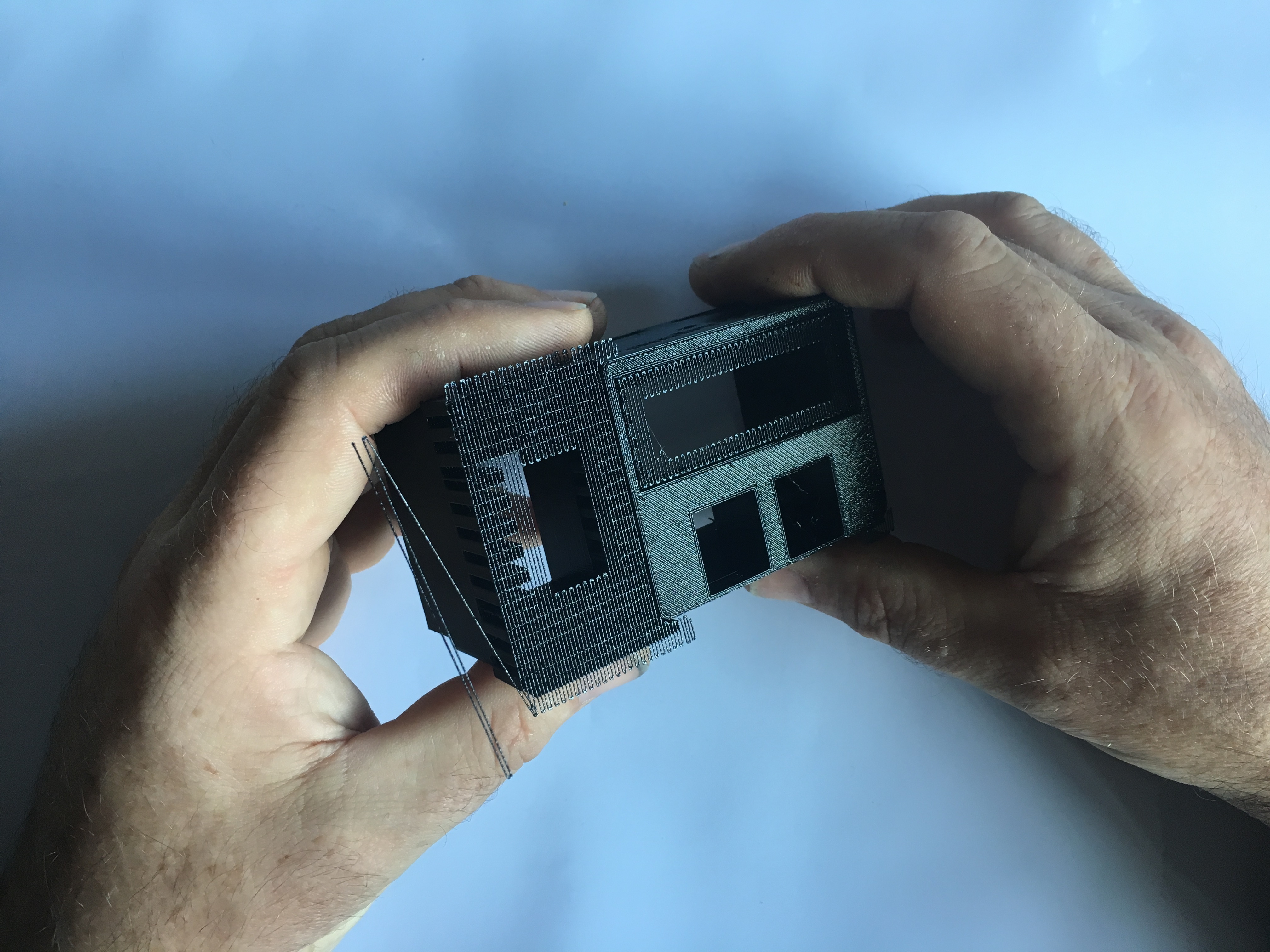
Gently remove support material
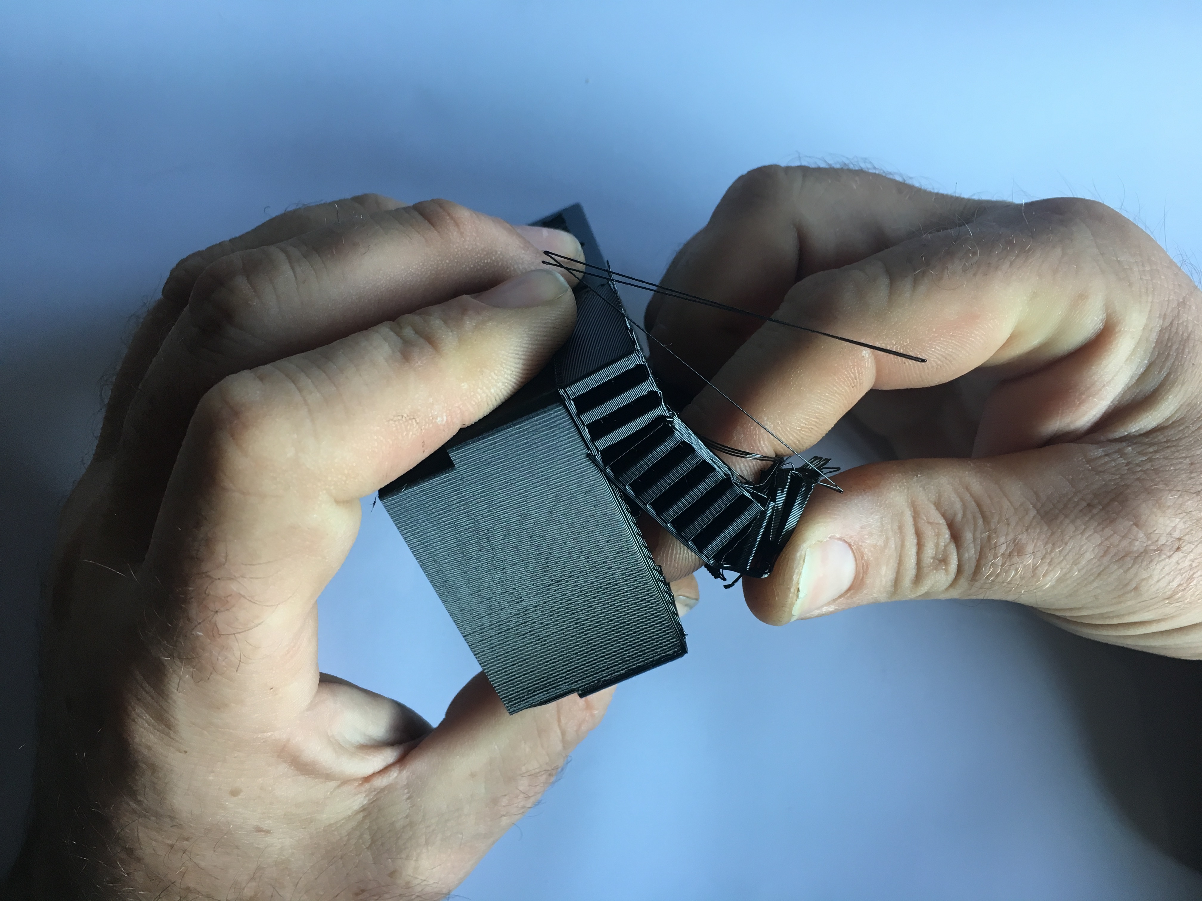
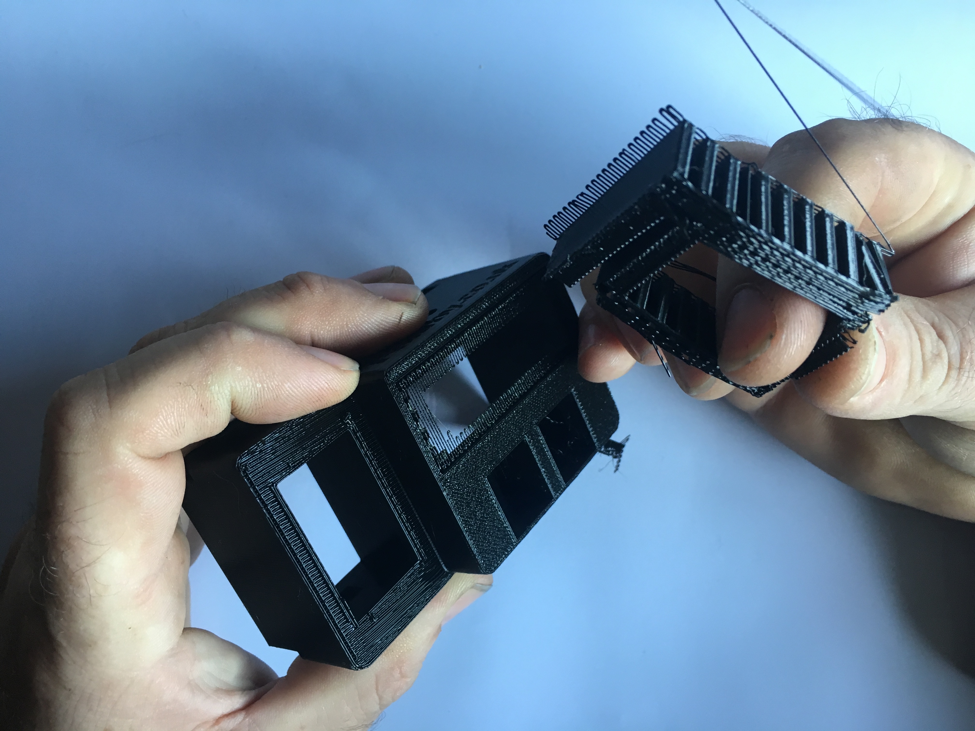
Gently remove support material
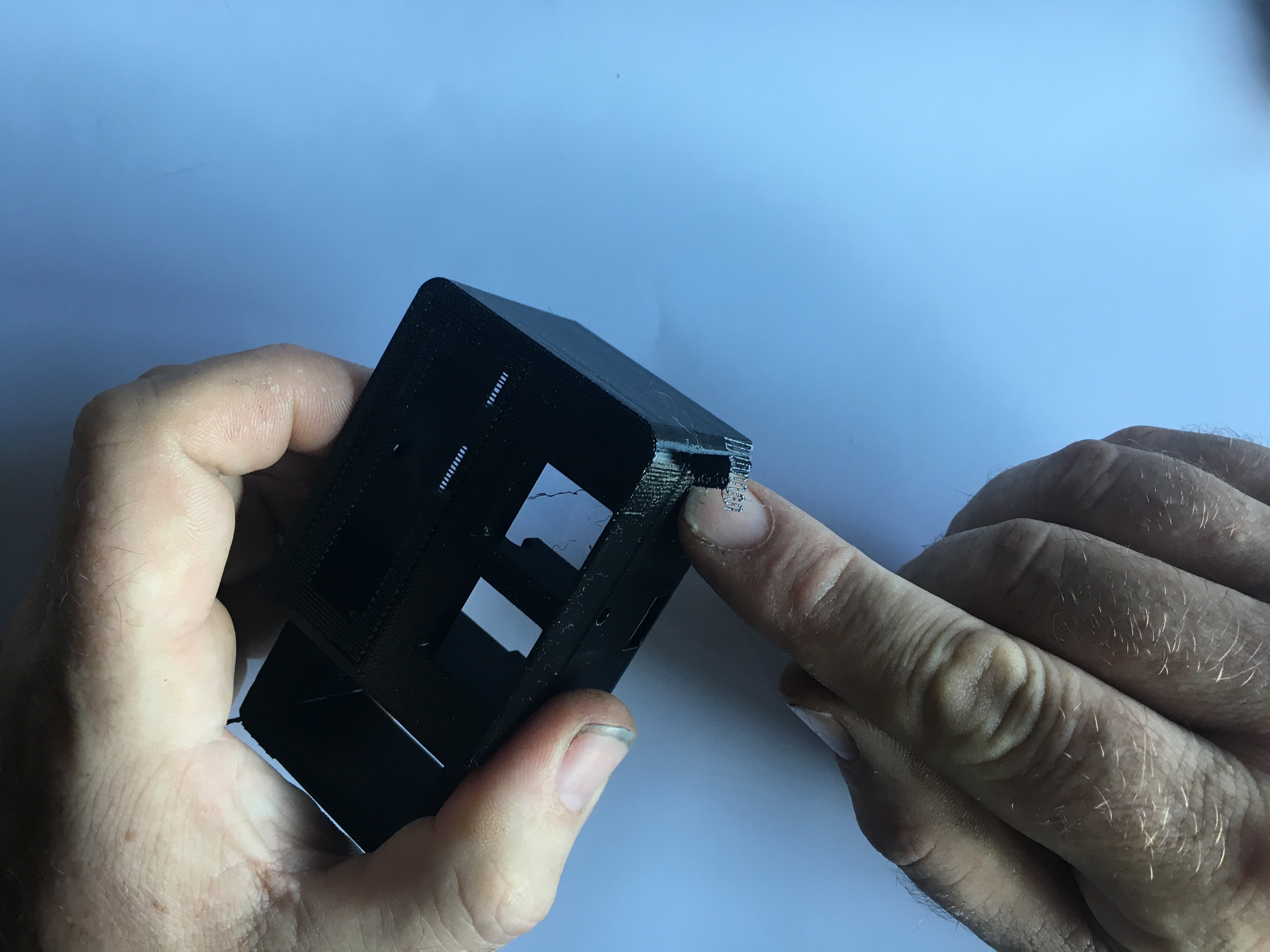
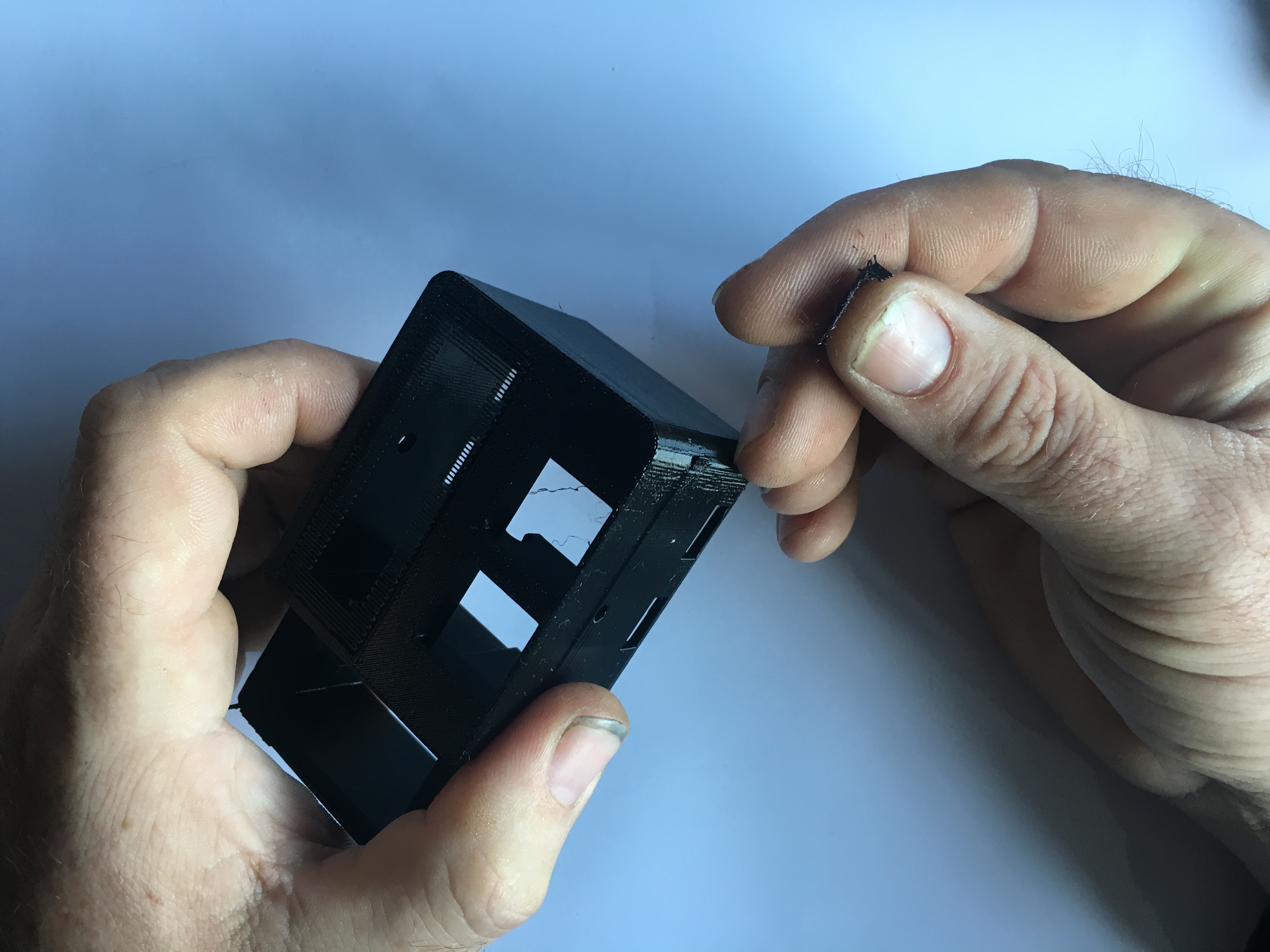
Gently remove support material
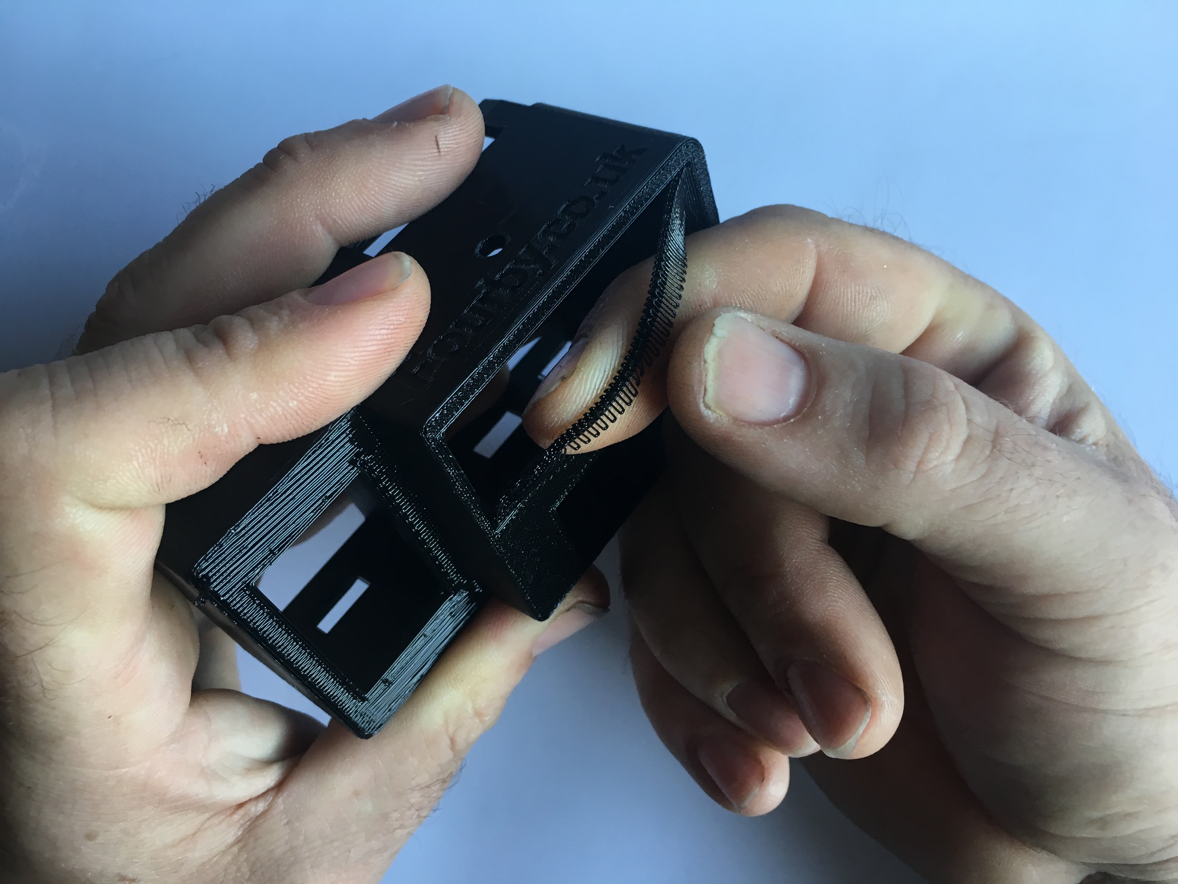
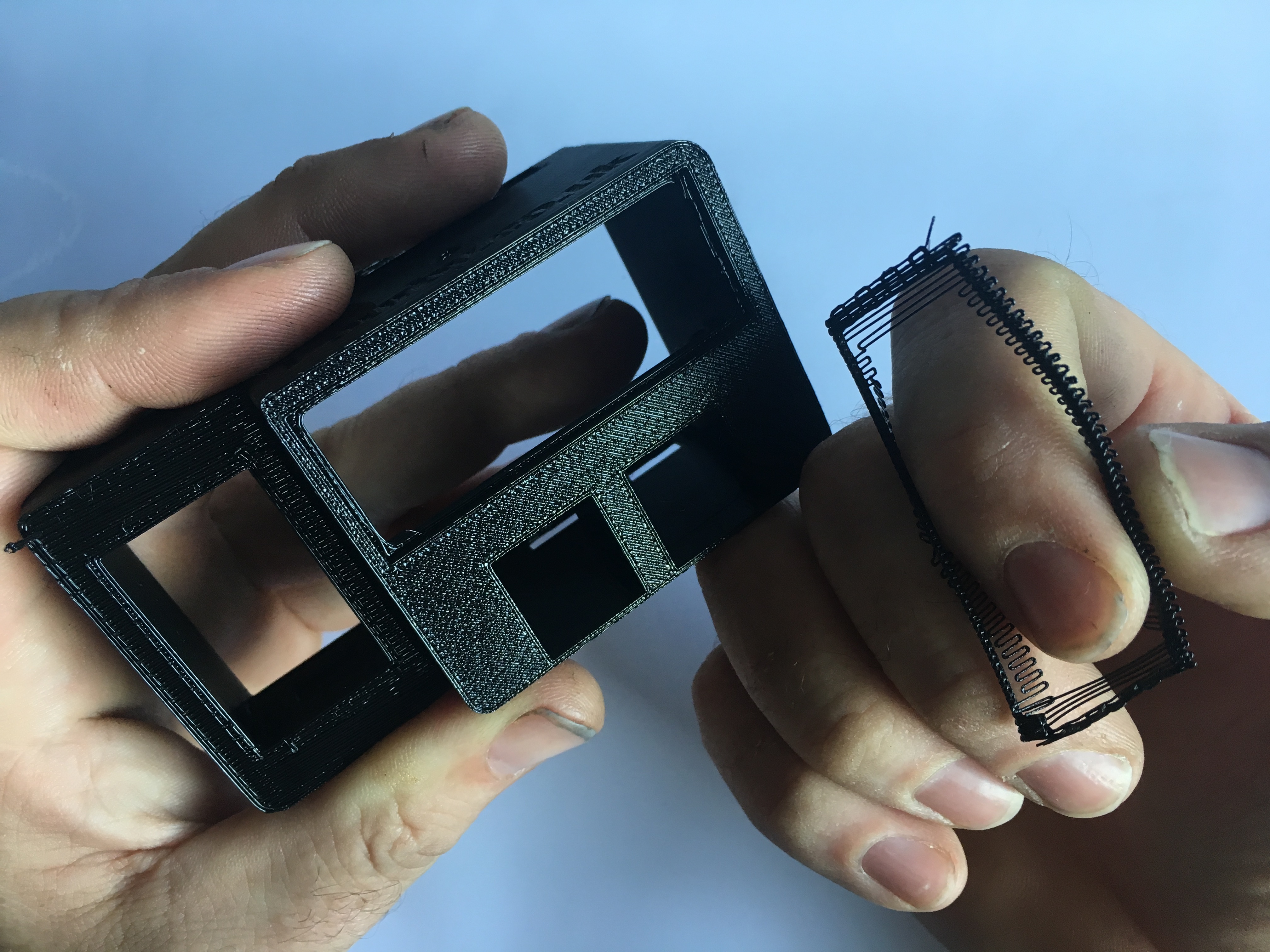
Cleanup Complete, on to the the next bit....
![]()
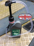
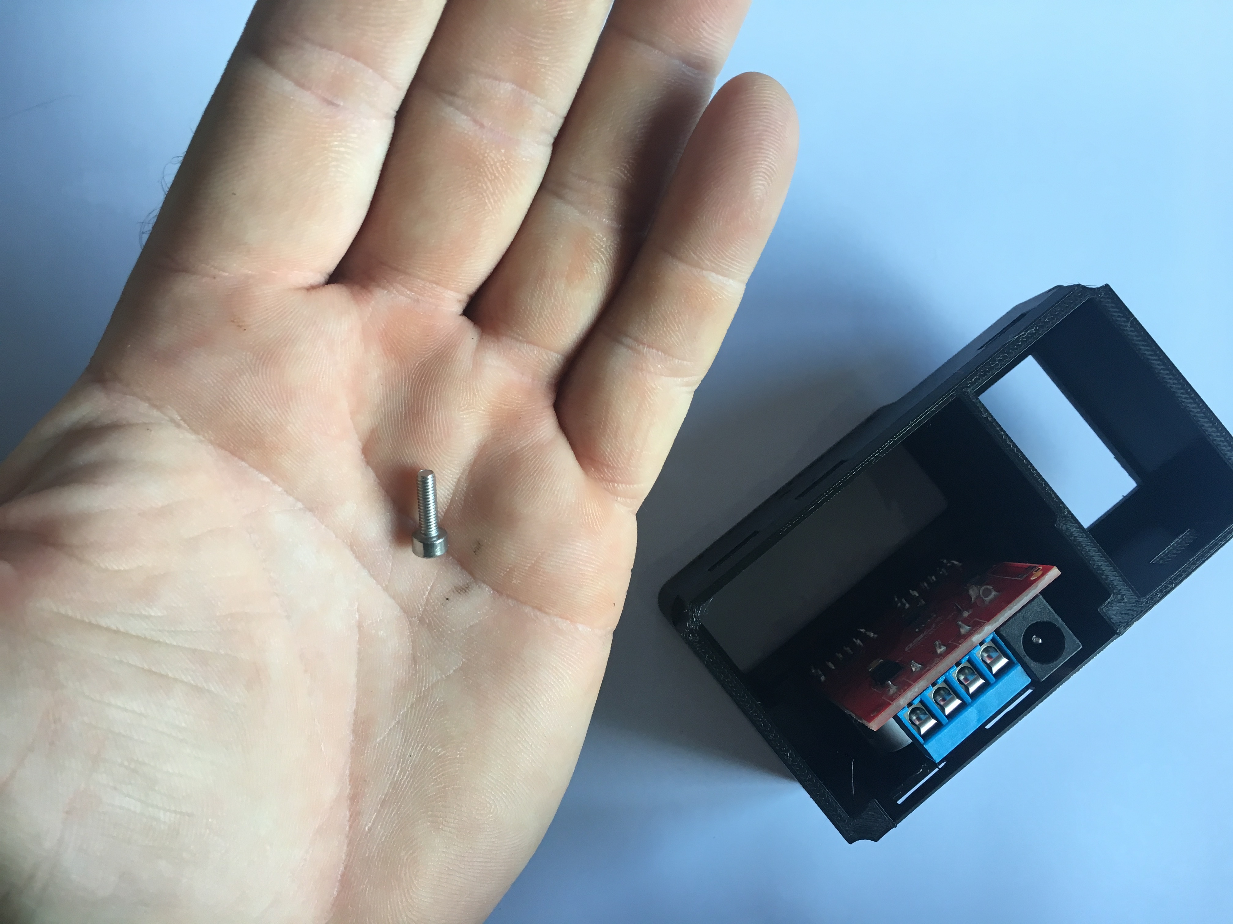
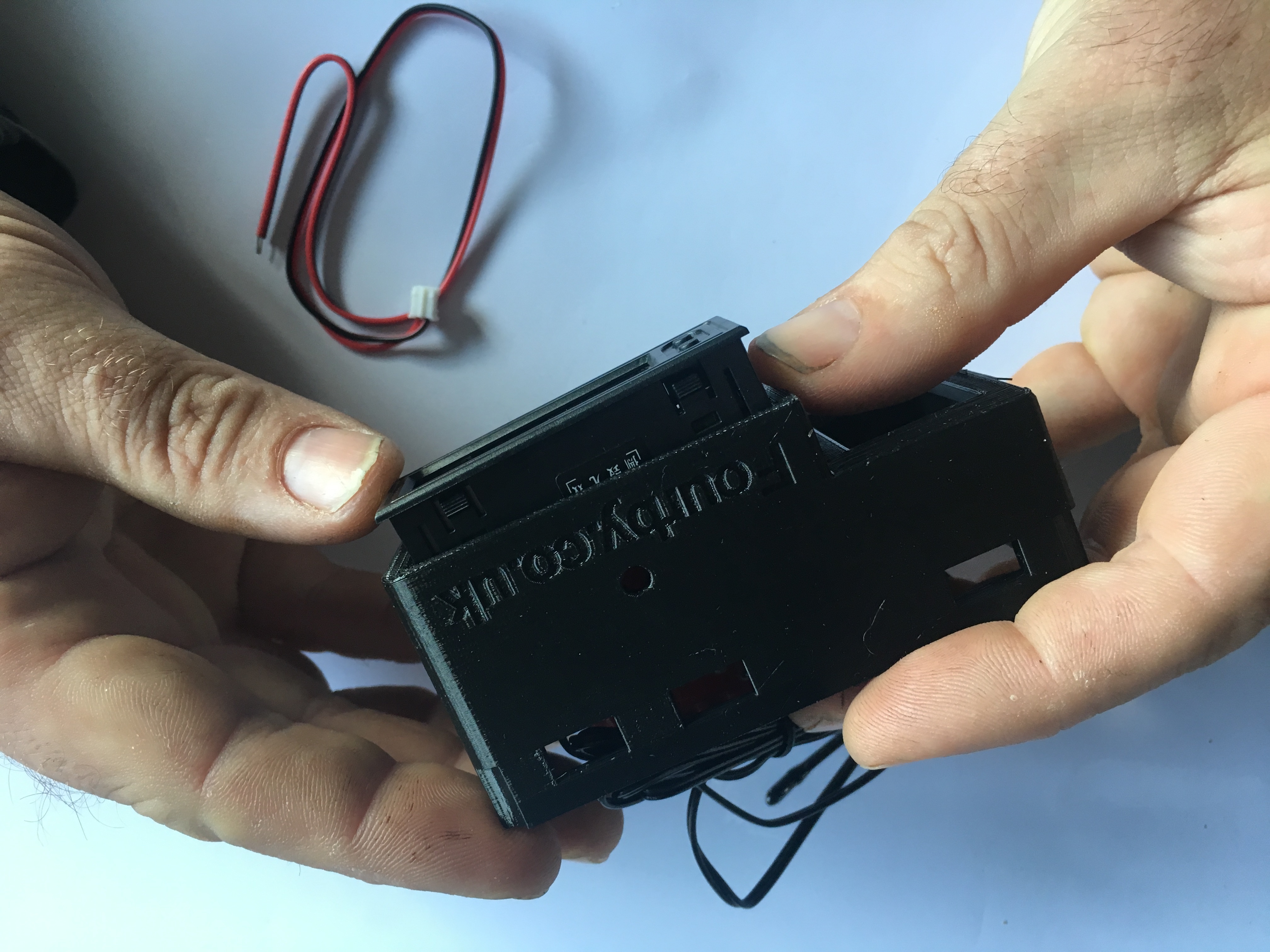
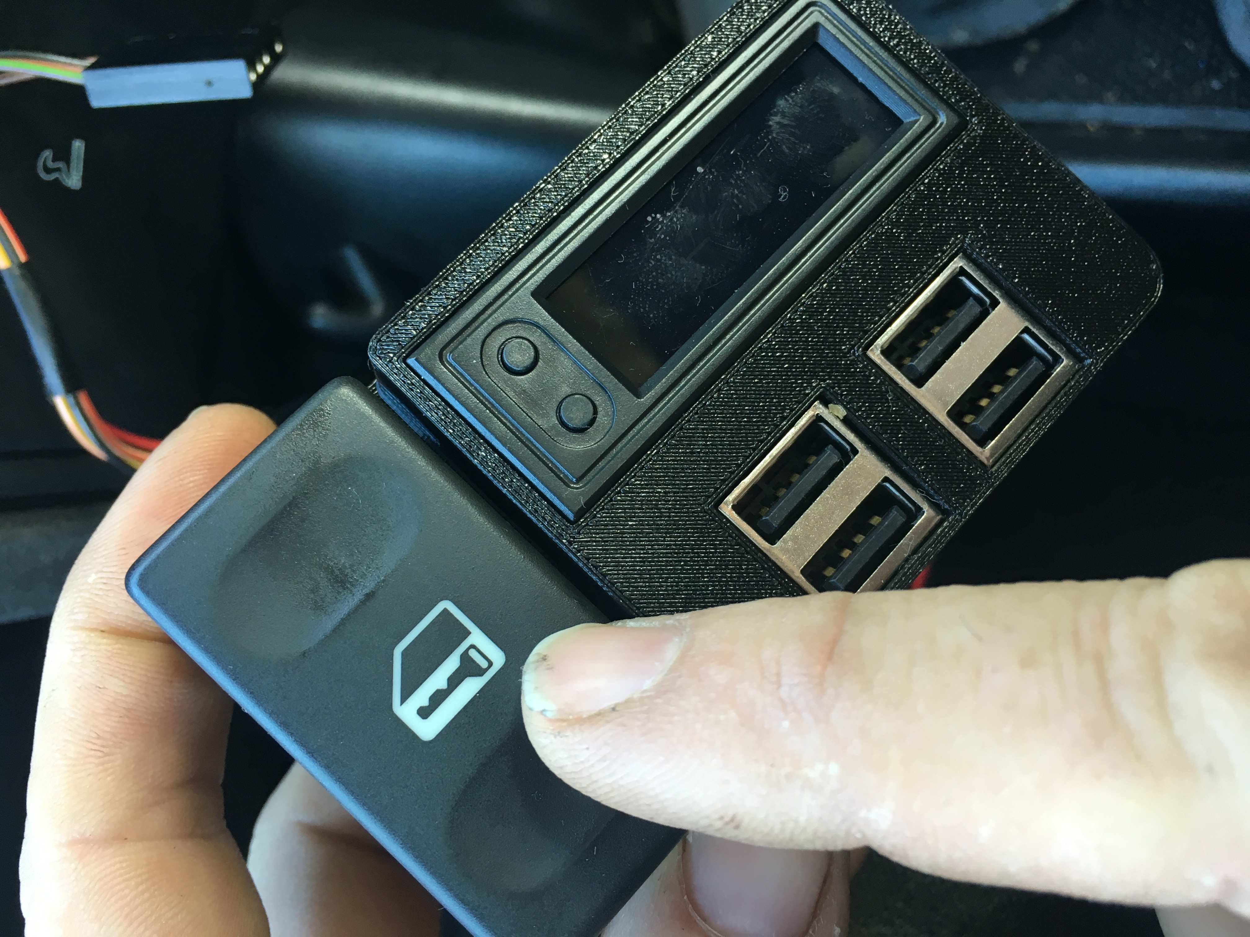
Find the USB Module from your parts bag
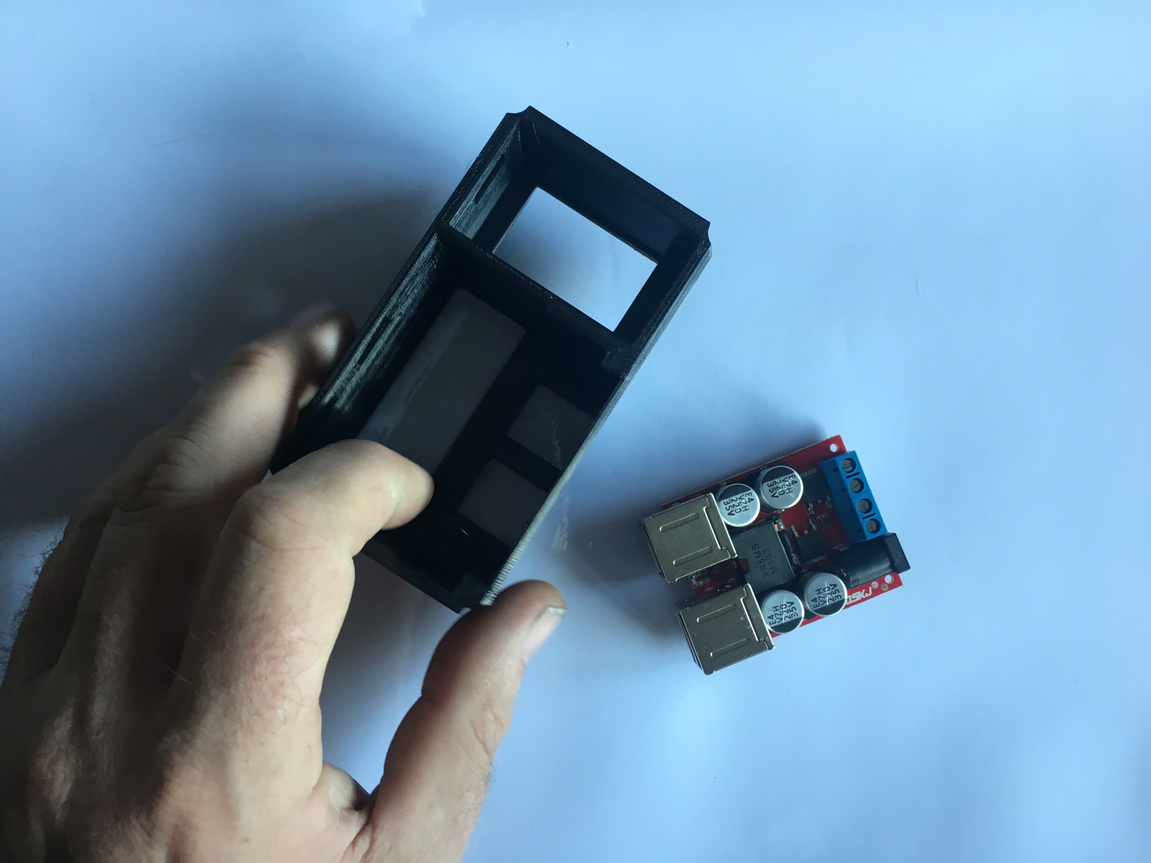
face down on a flat surface, add in the USB module
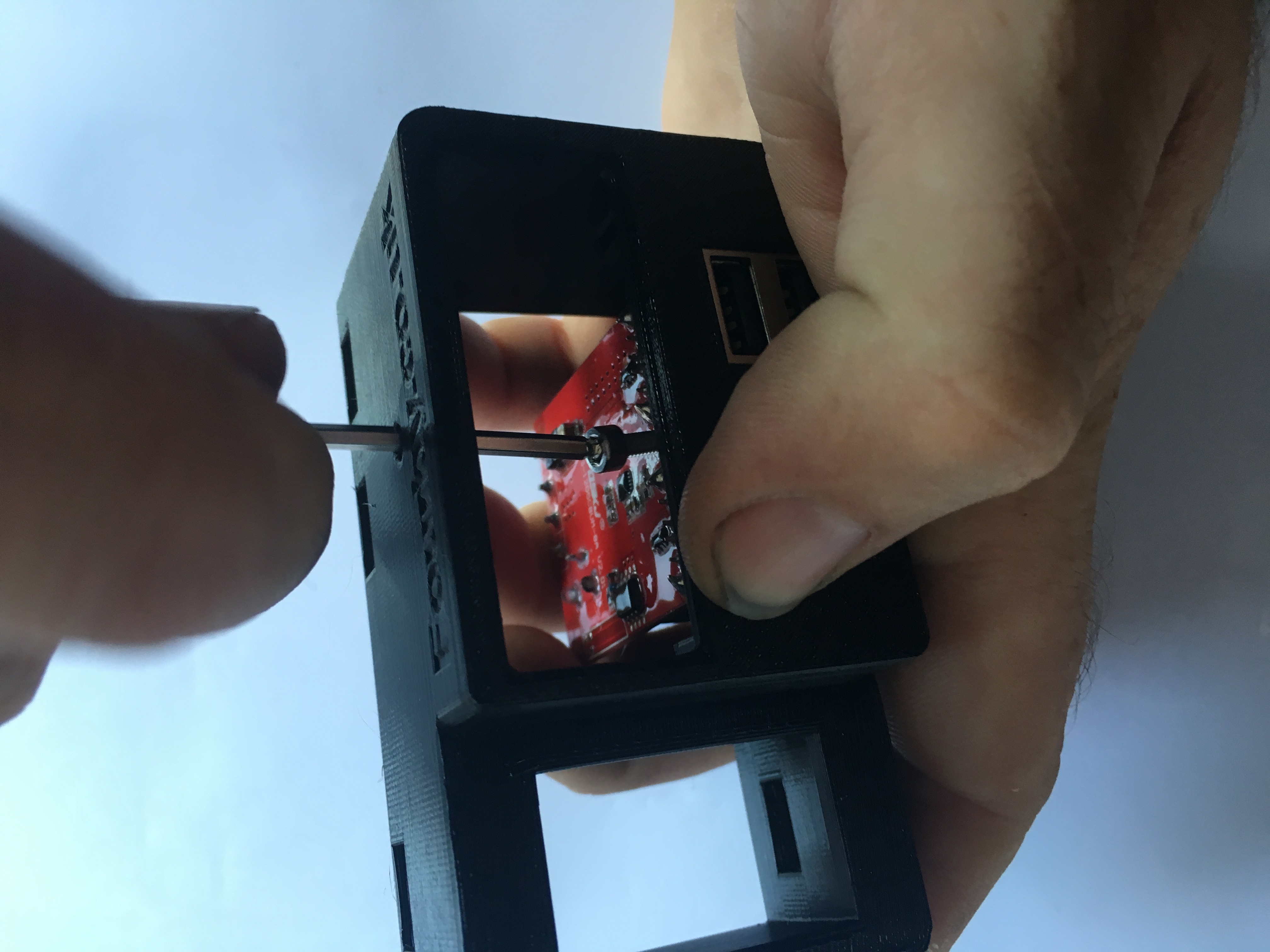
Find your retaining Screw from your parts bag
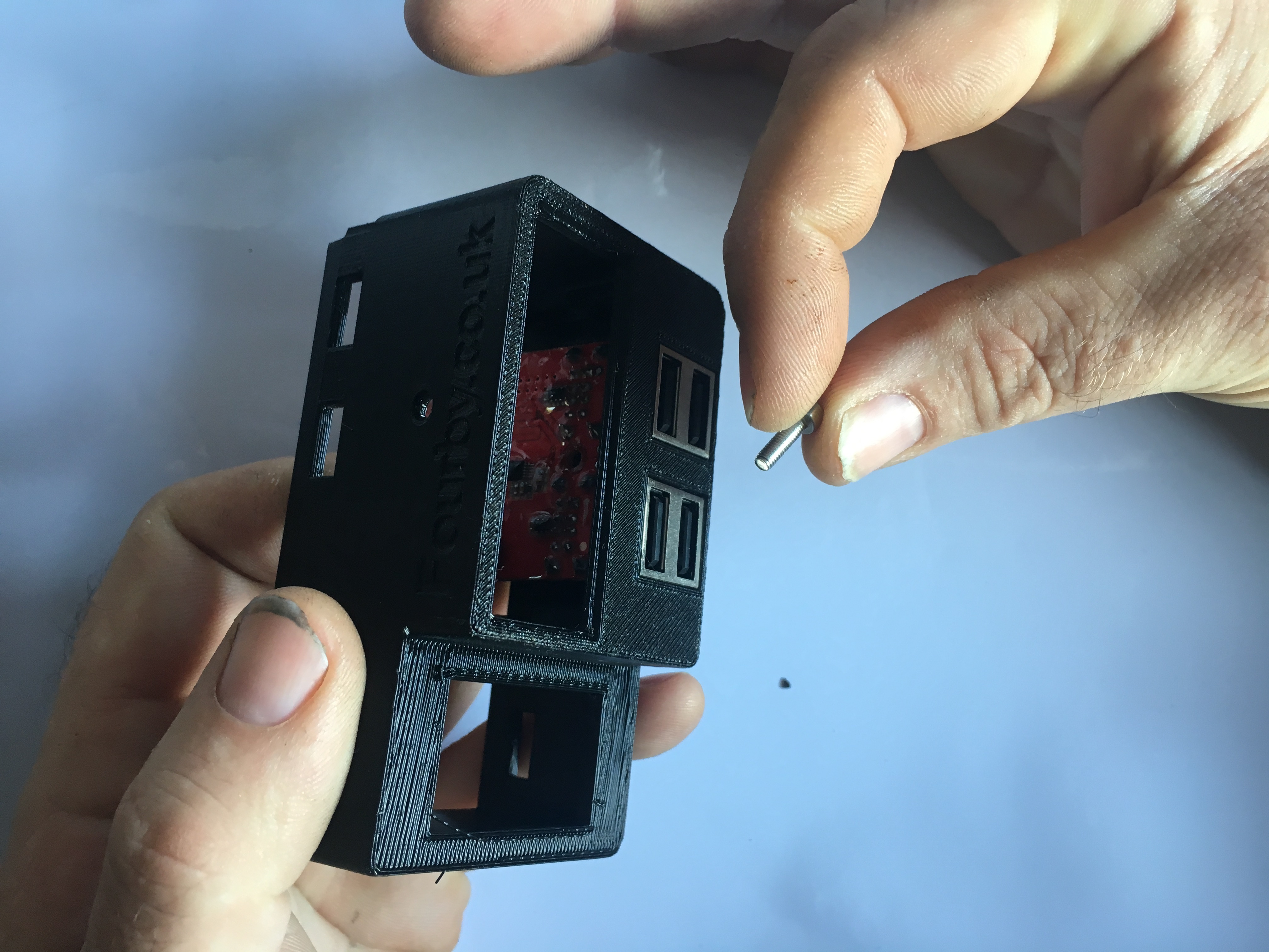
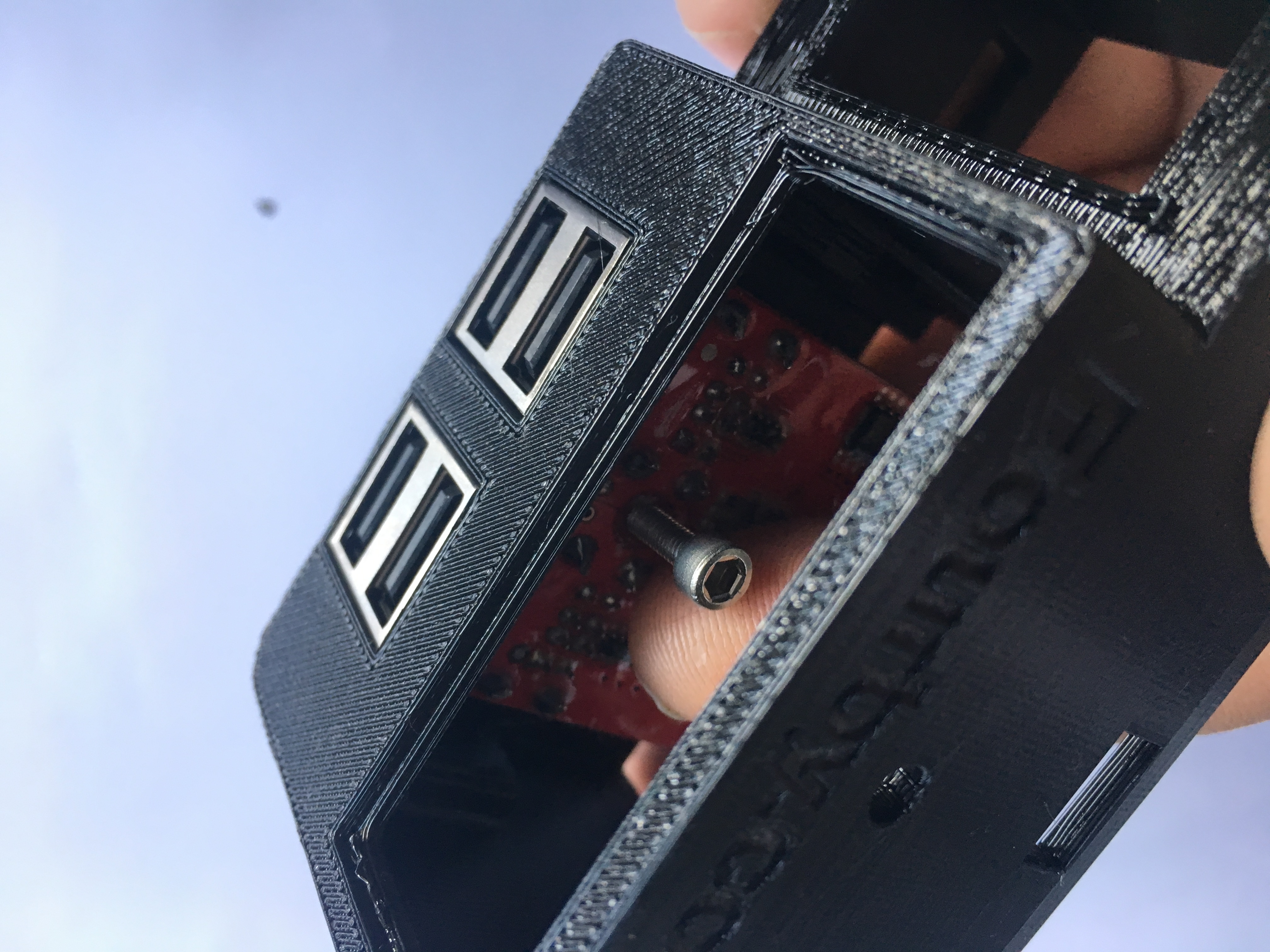
Using a 2.5mm Allen Key Add the screw.
Important: There are no threads already, the screw will cut its own thread, take your time and allow the screw to bite and draw itself down, dont rush, its a very fine thread, torque up the screw just enough for it to be tight but dont overtighten and destroy the threads. Needle nose pliers may help here.
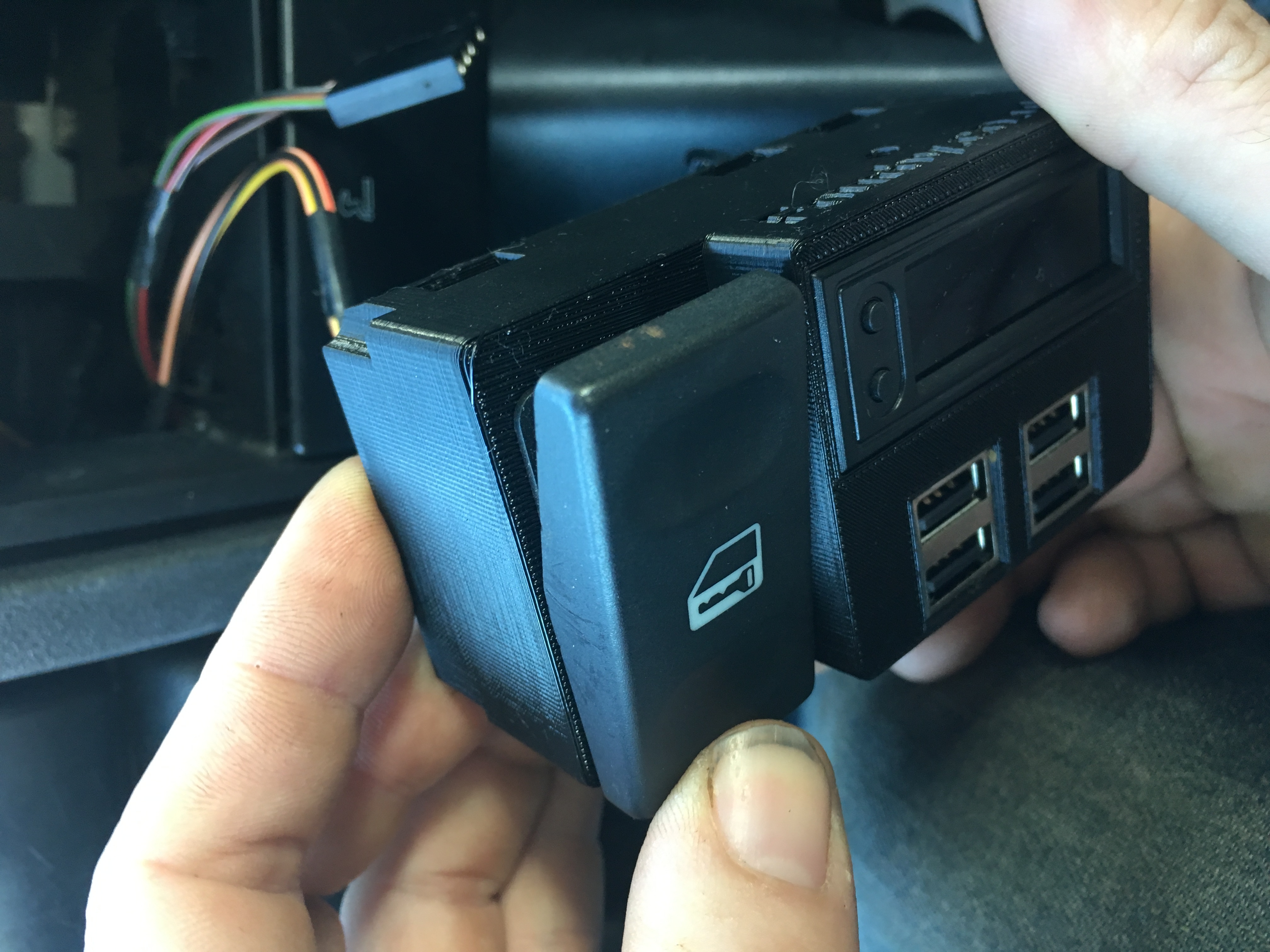
USB Module done, on to the next bit....
![]()
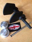
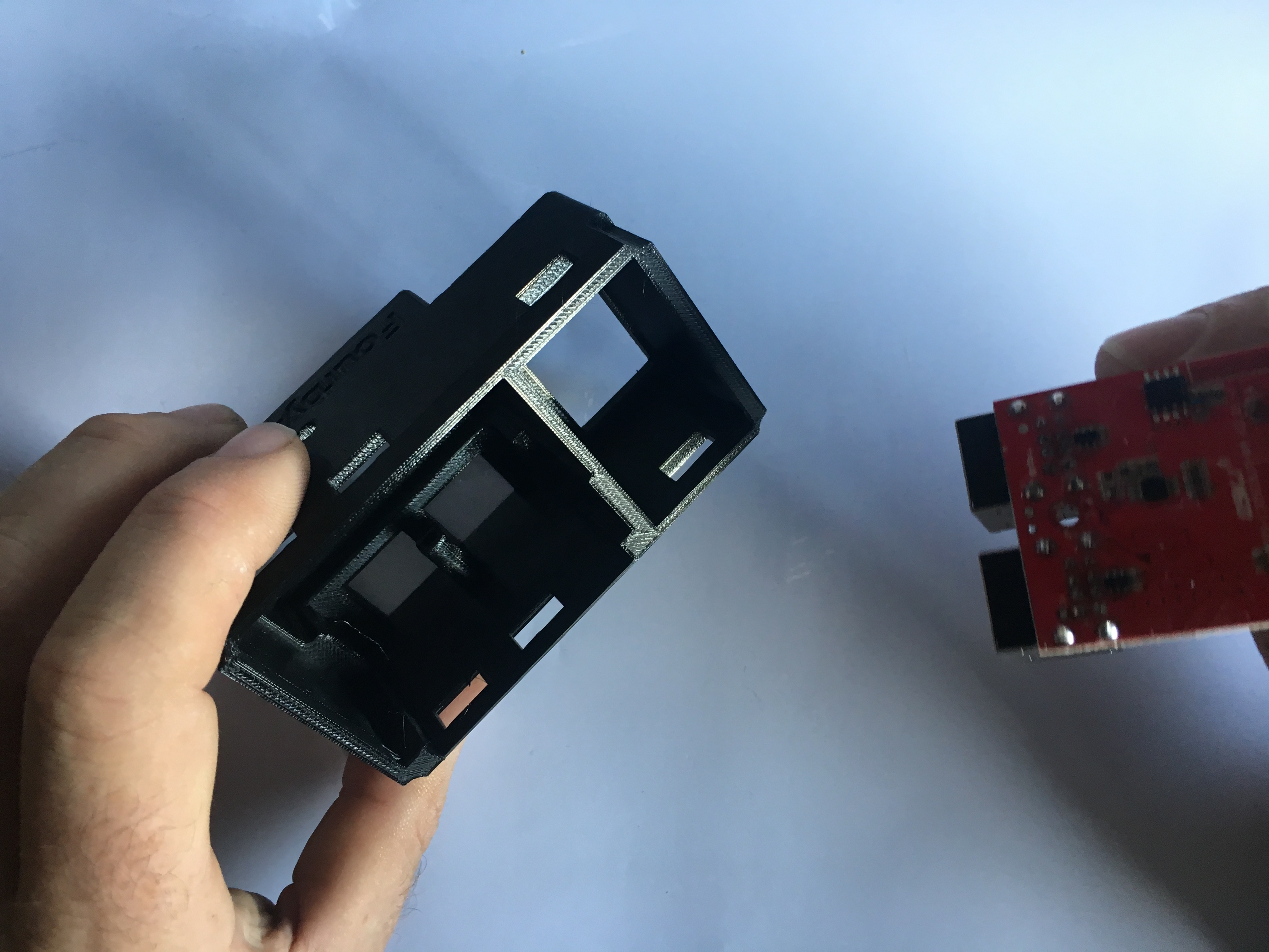
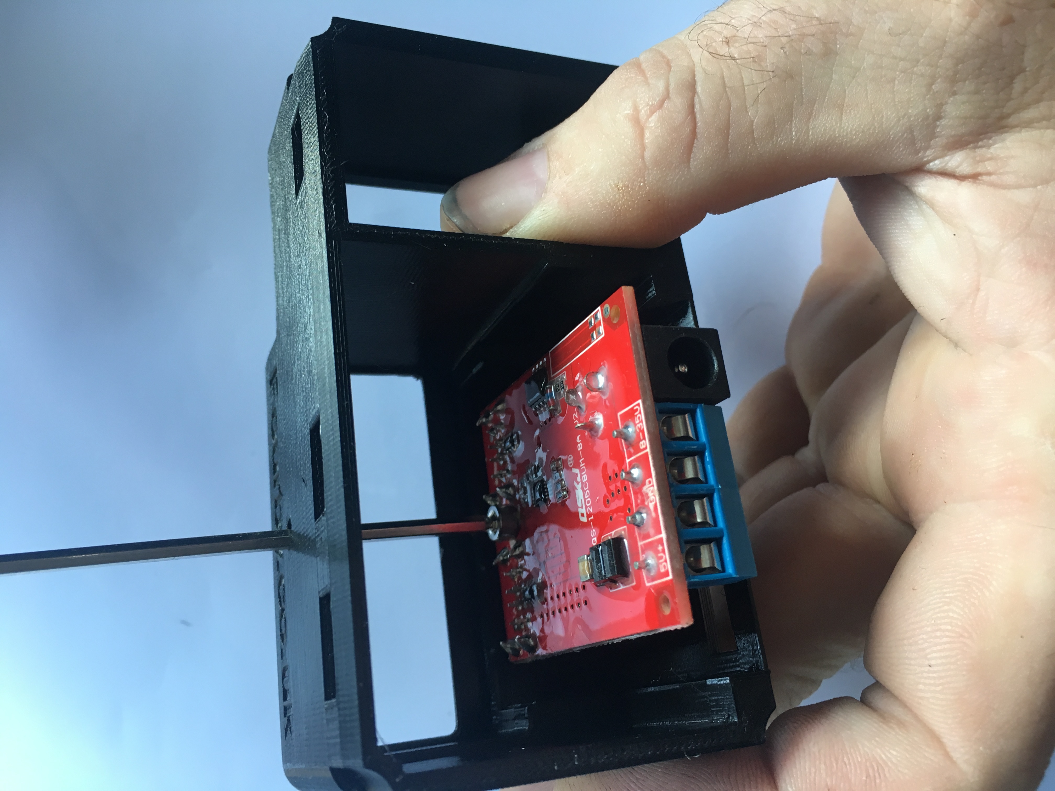
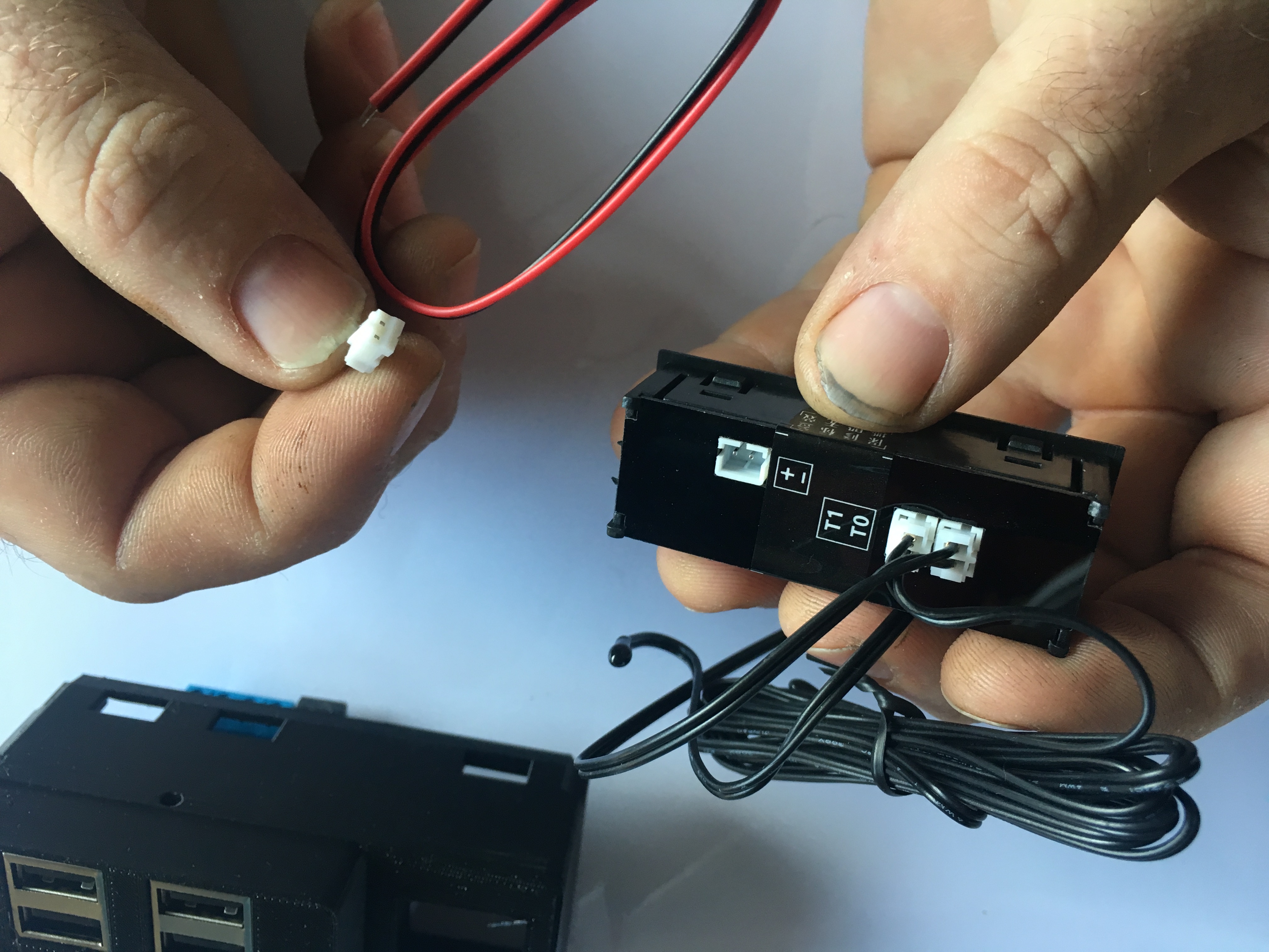
Find the Clock Module from your parts bag
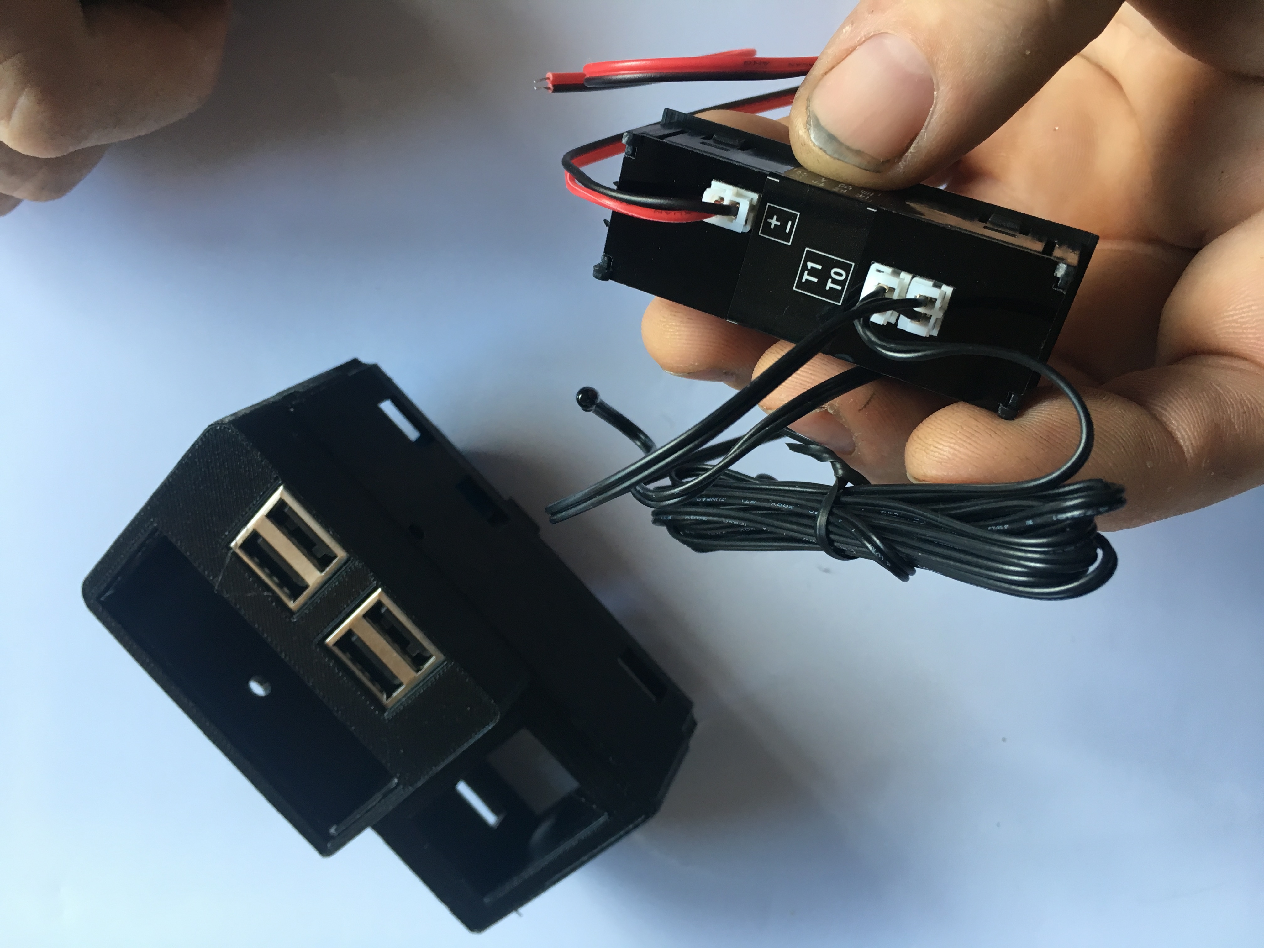
Gently Pinch the white power plug connector from the clock and remove the power cable for now
Offer the clock into position being carefull about the orientation, thread the temp probes though
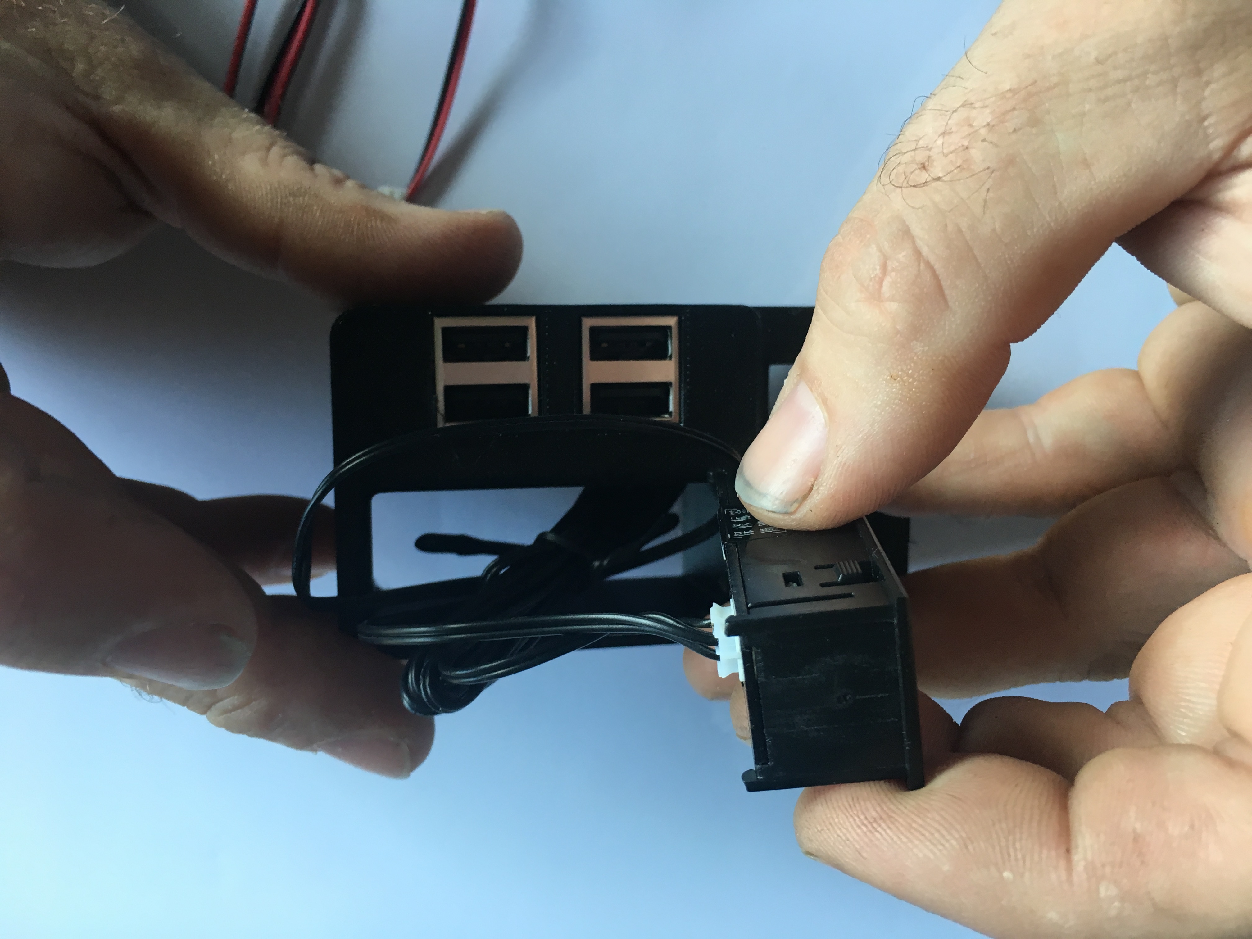
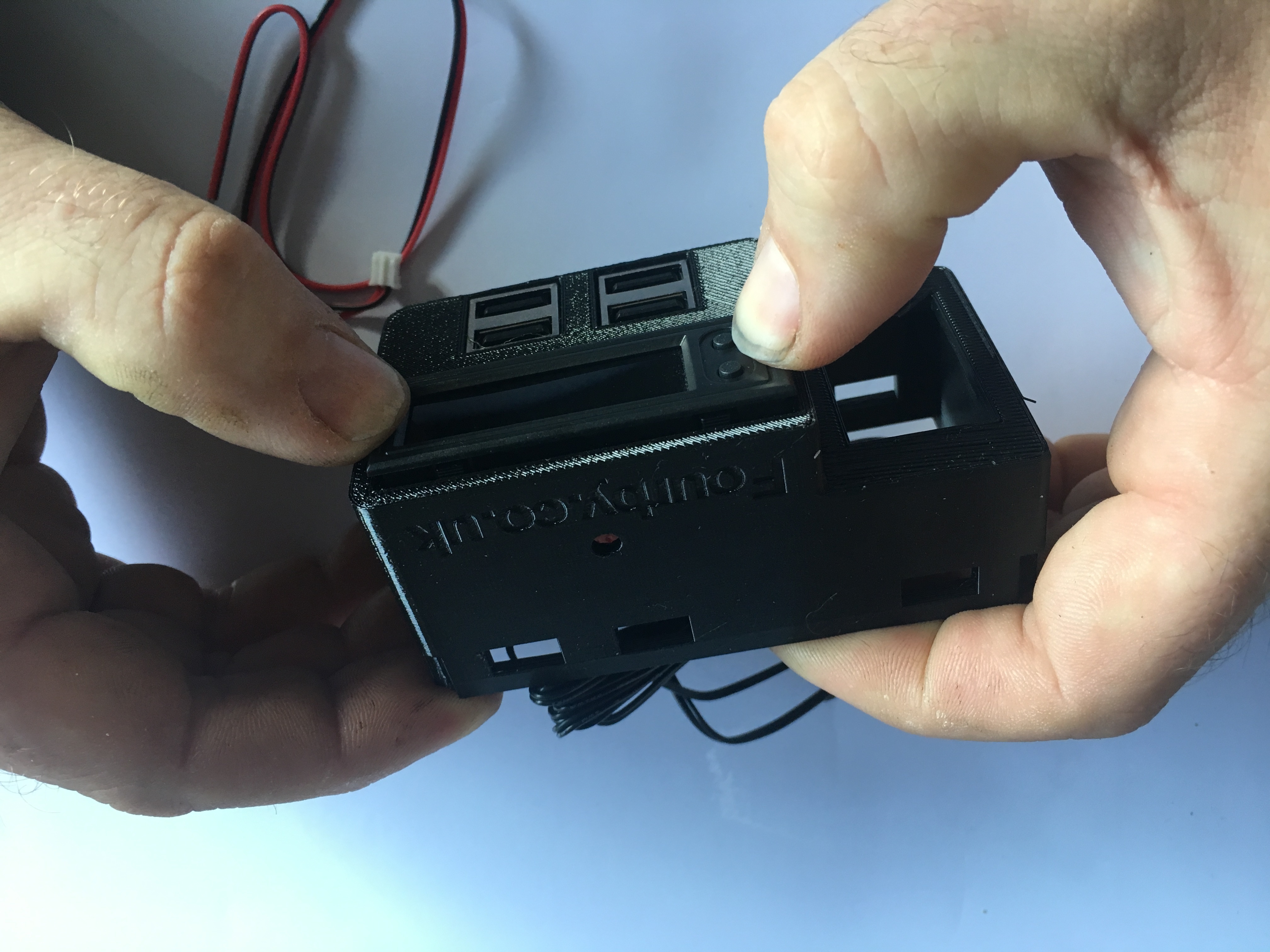
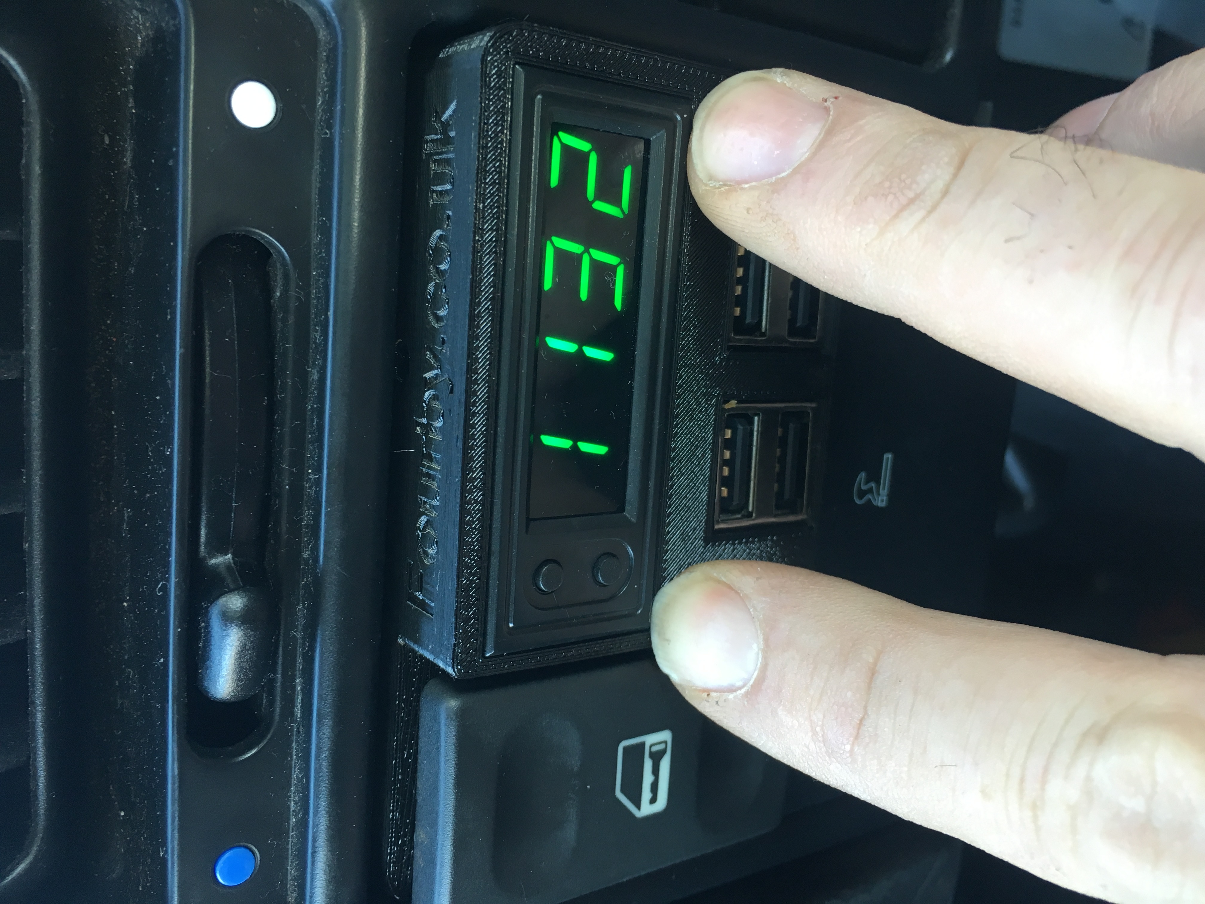
Make sure the two clock buttons are in the upper left and click the clock module into place
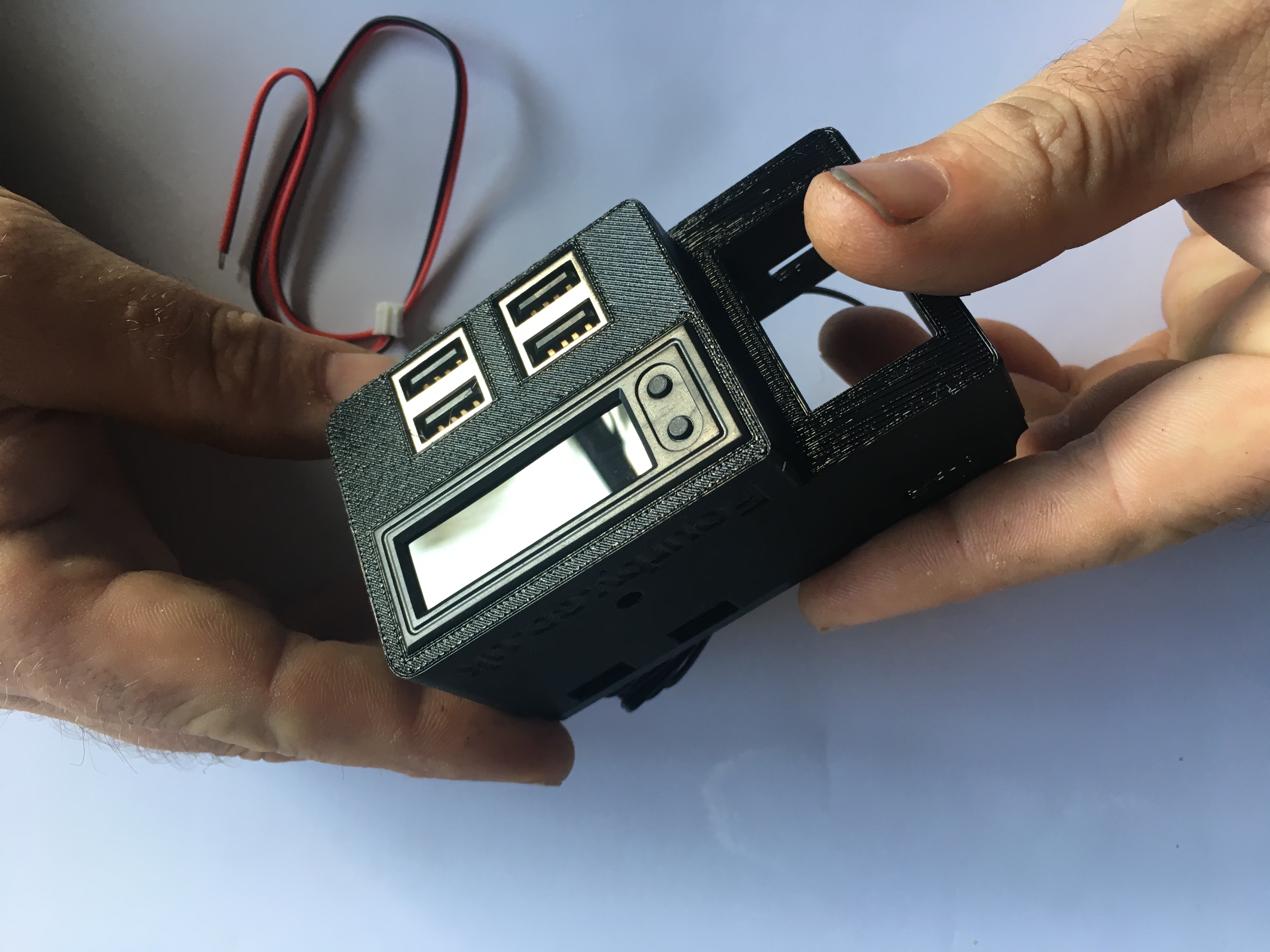
Clock Module done, on to the next bit.
![]()
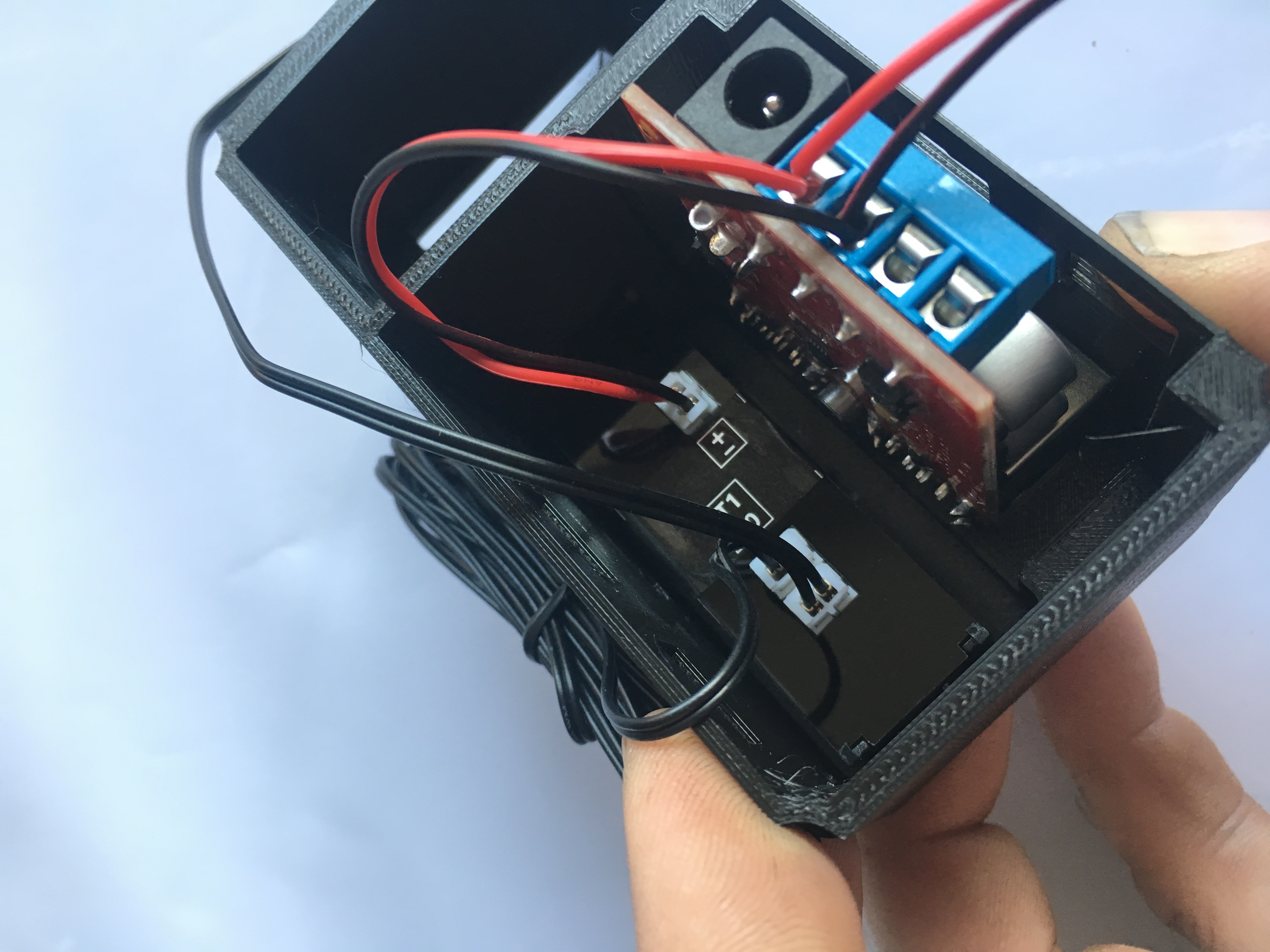
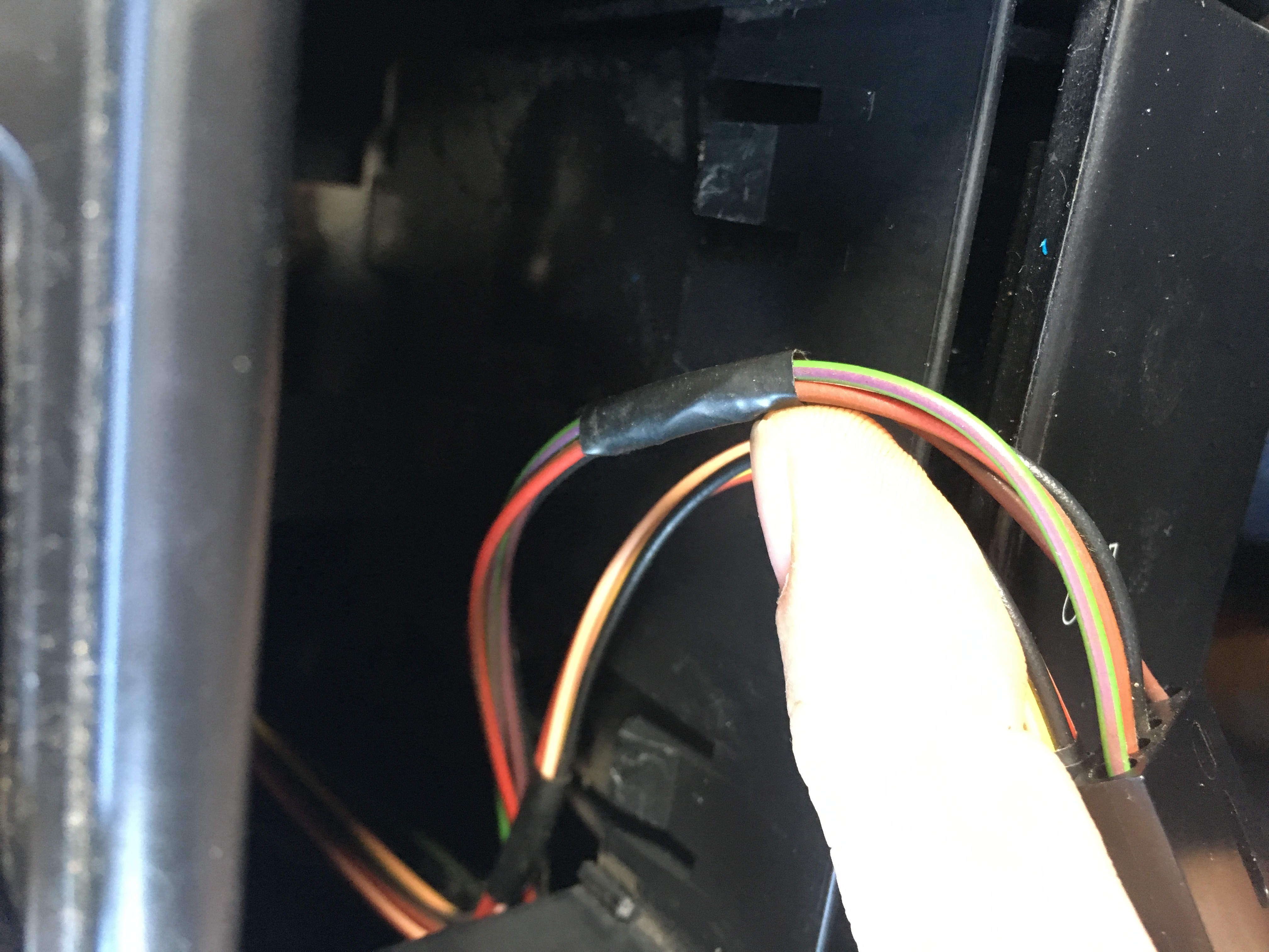
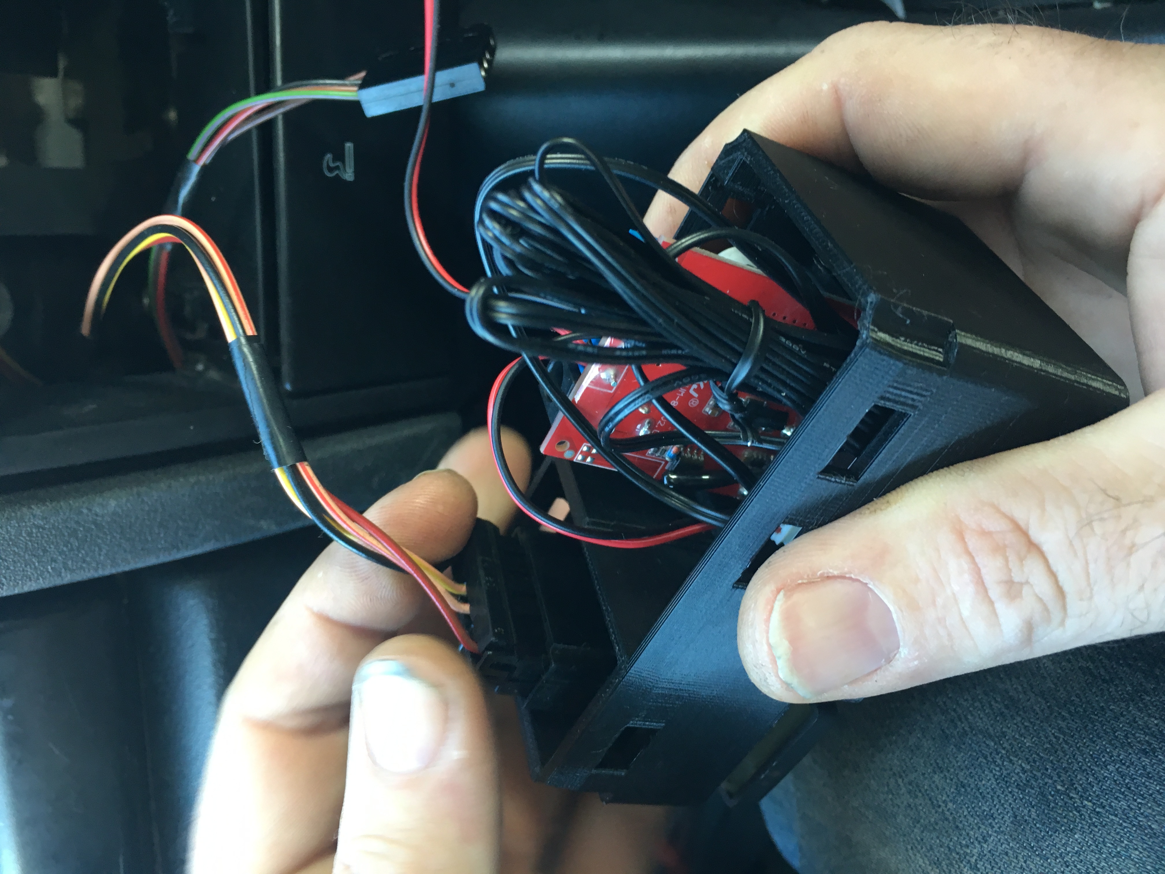
Next you will Wire the clock
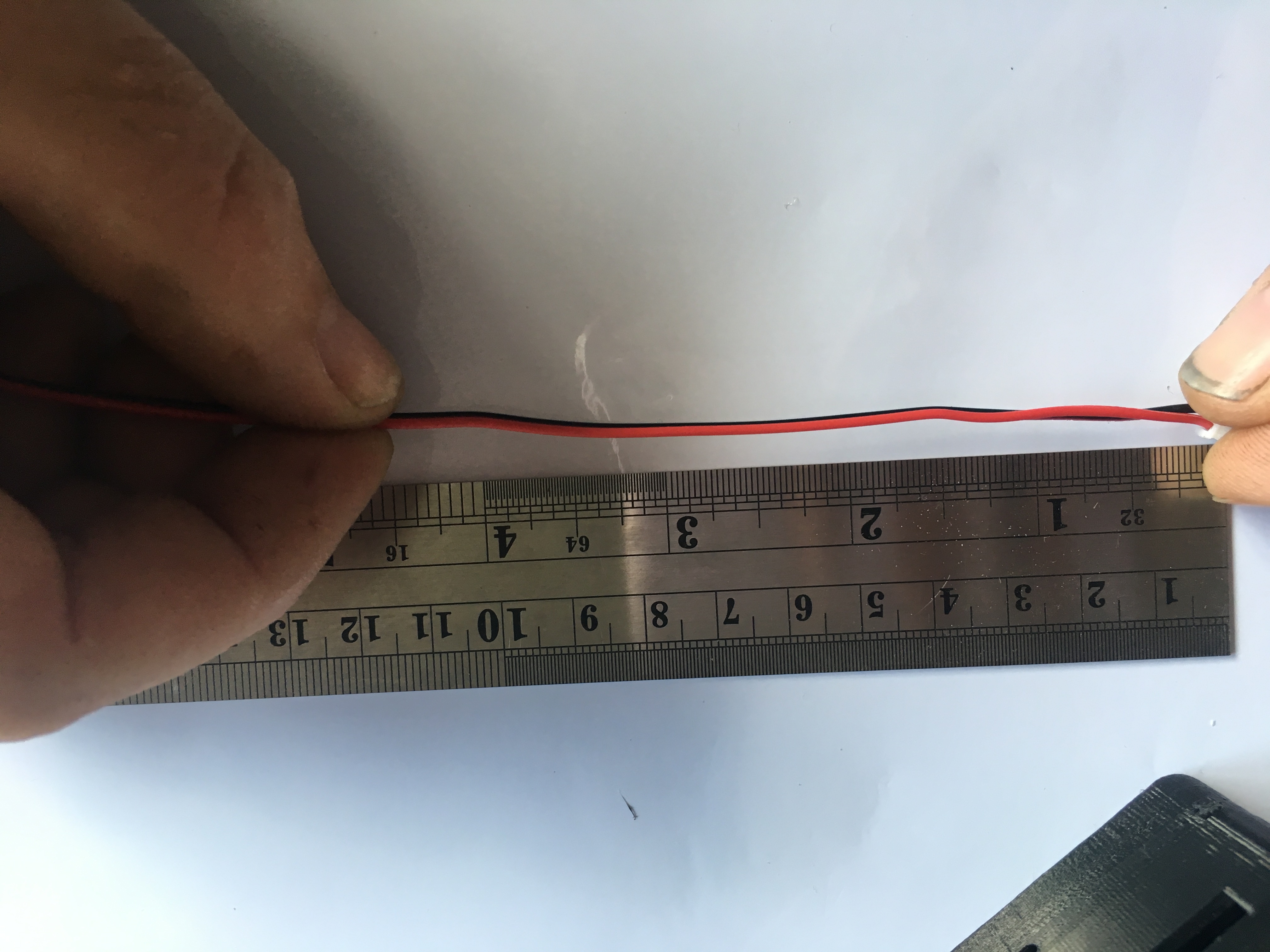
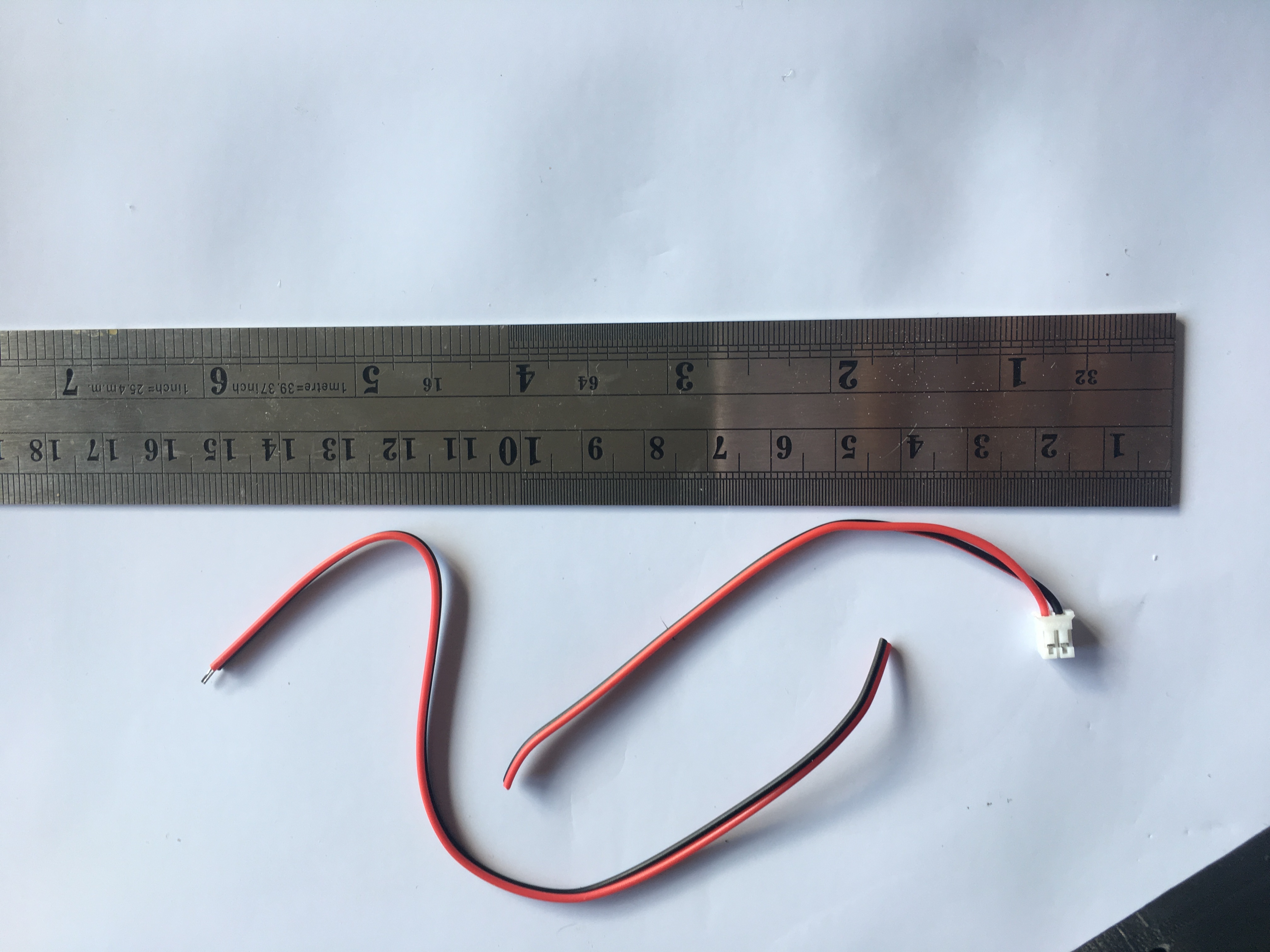
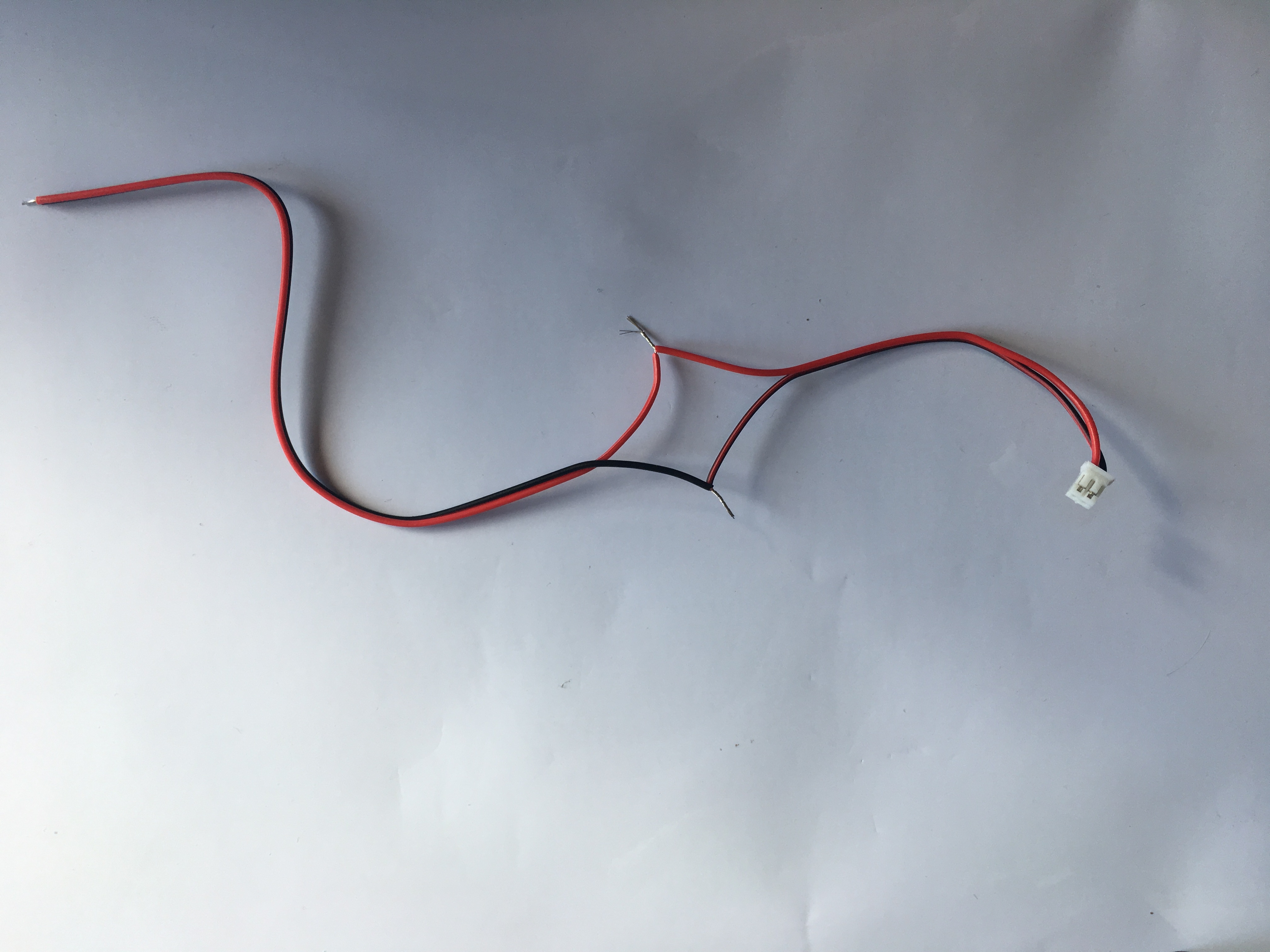
Take the power cable from the clock
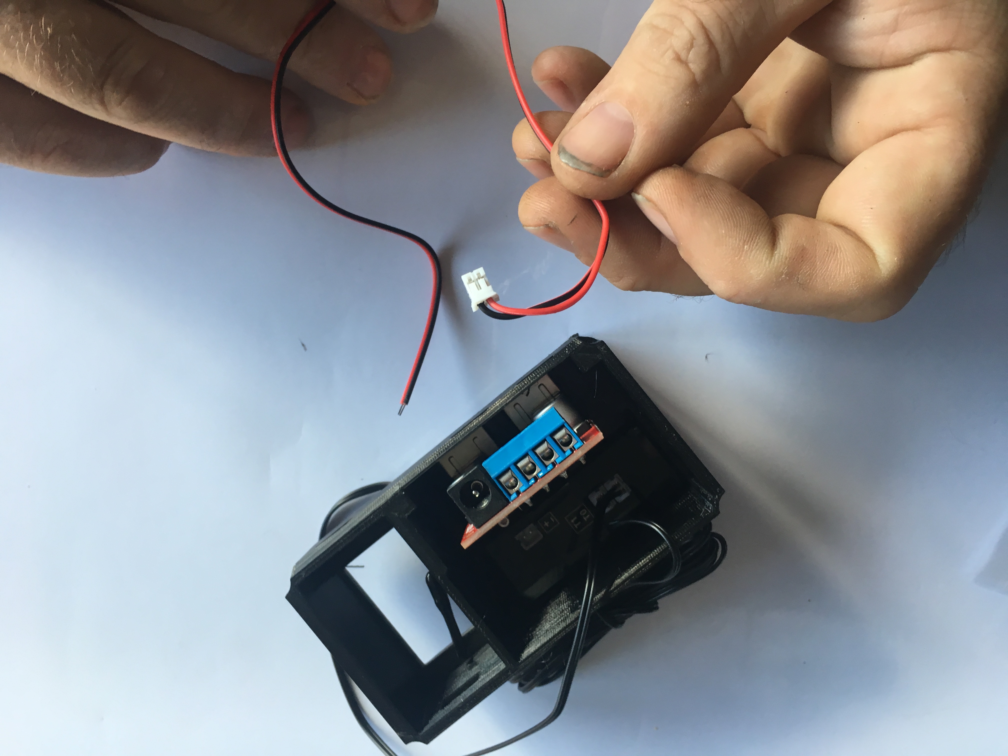
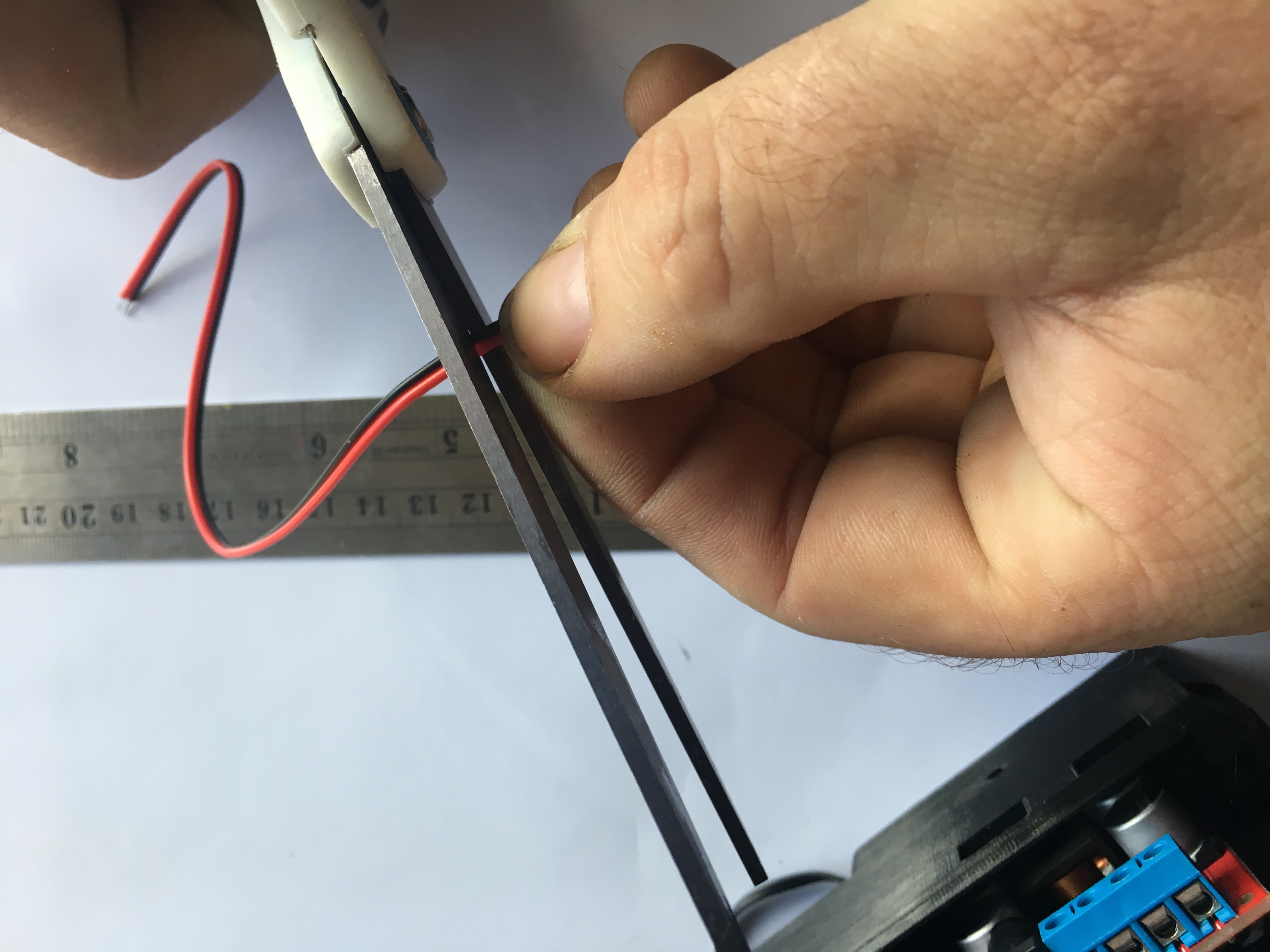
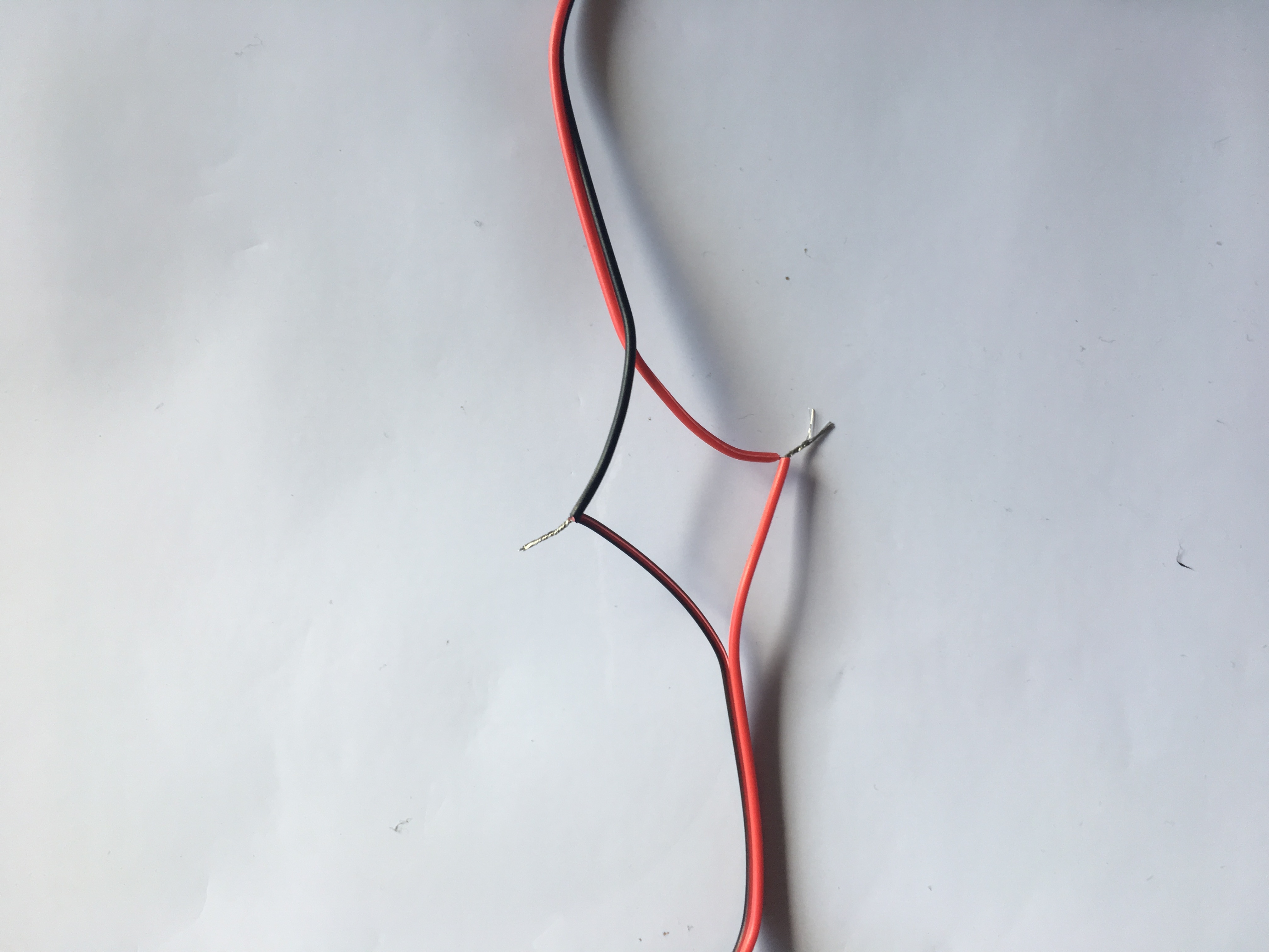
measure 4" from the white plug and cut it
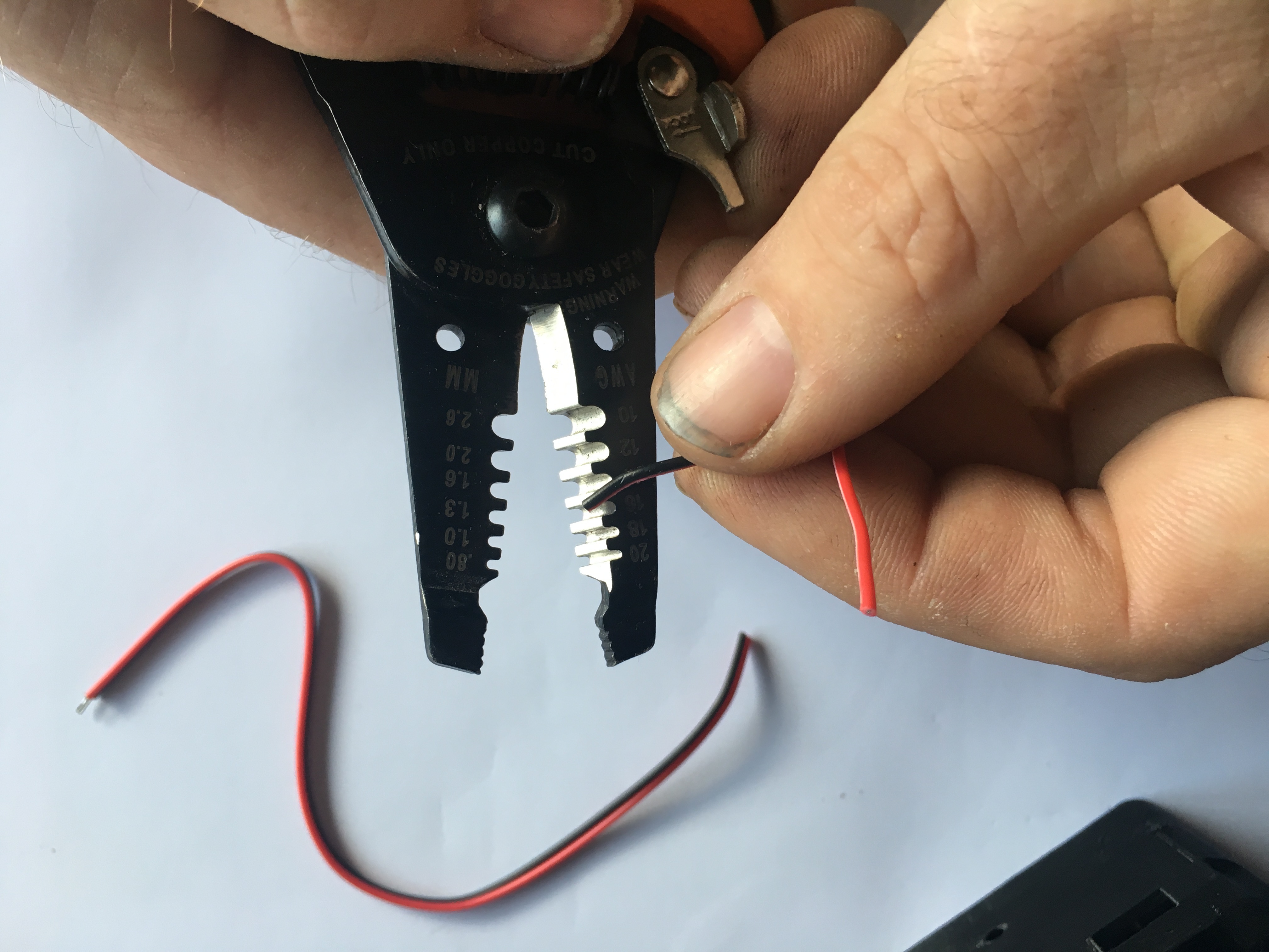
strip the new ends
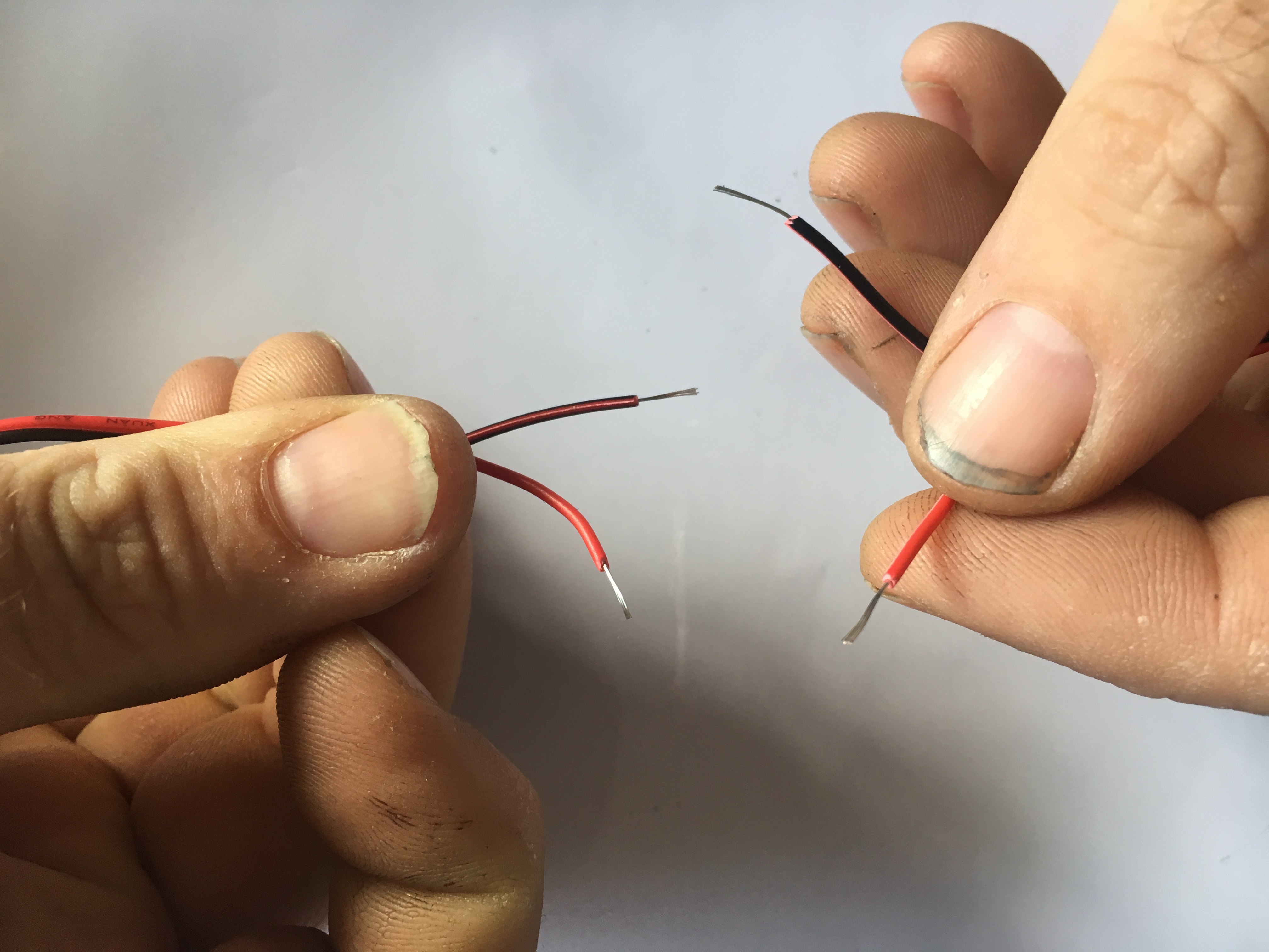
Twist them back together, Pay close attention to matching the correct colours back up
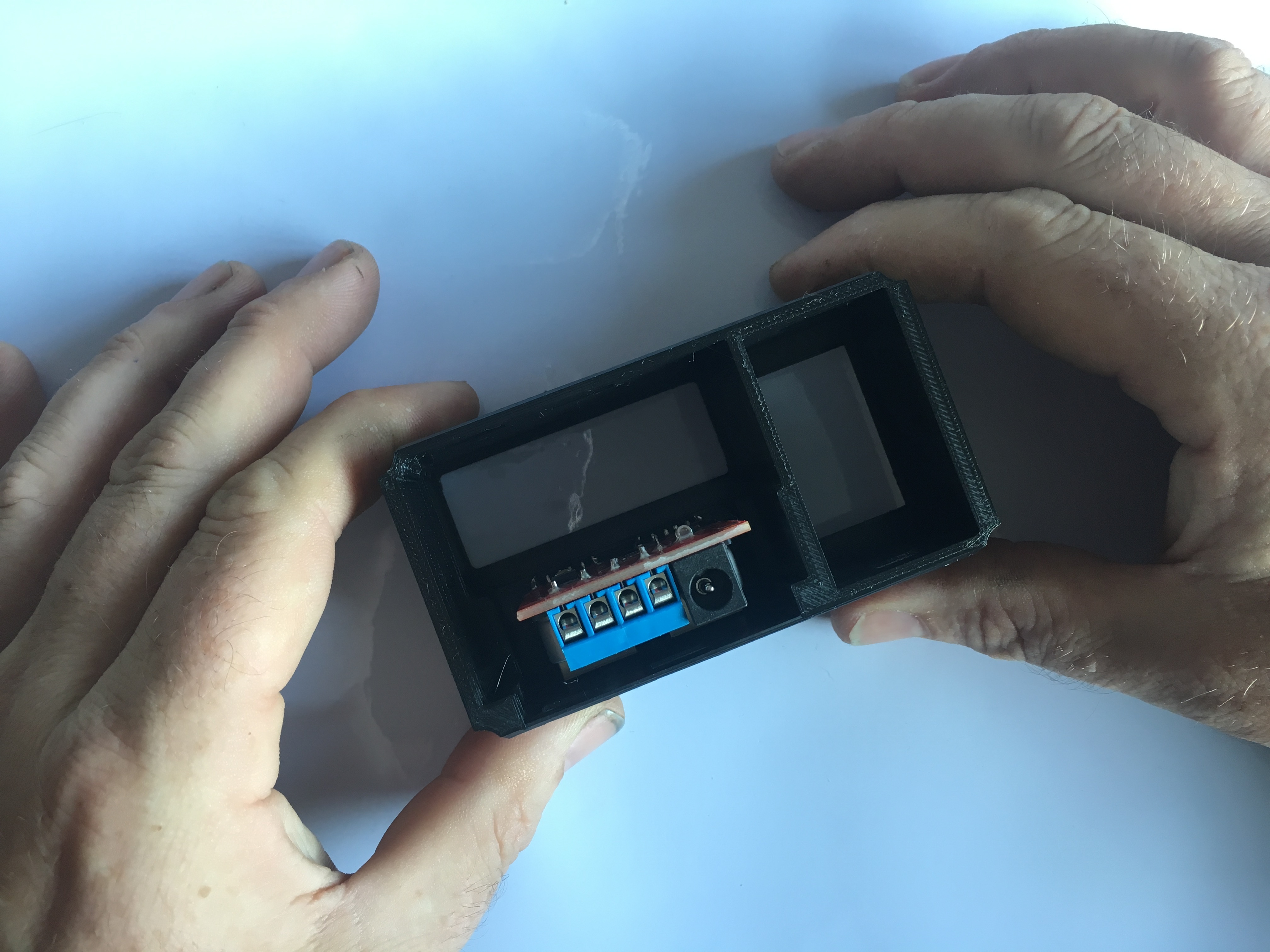
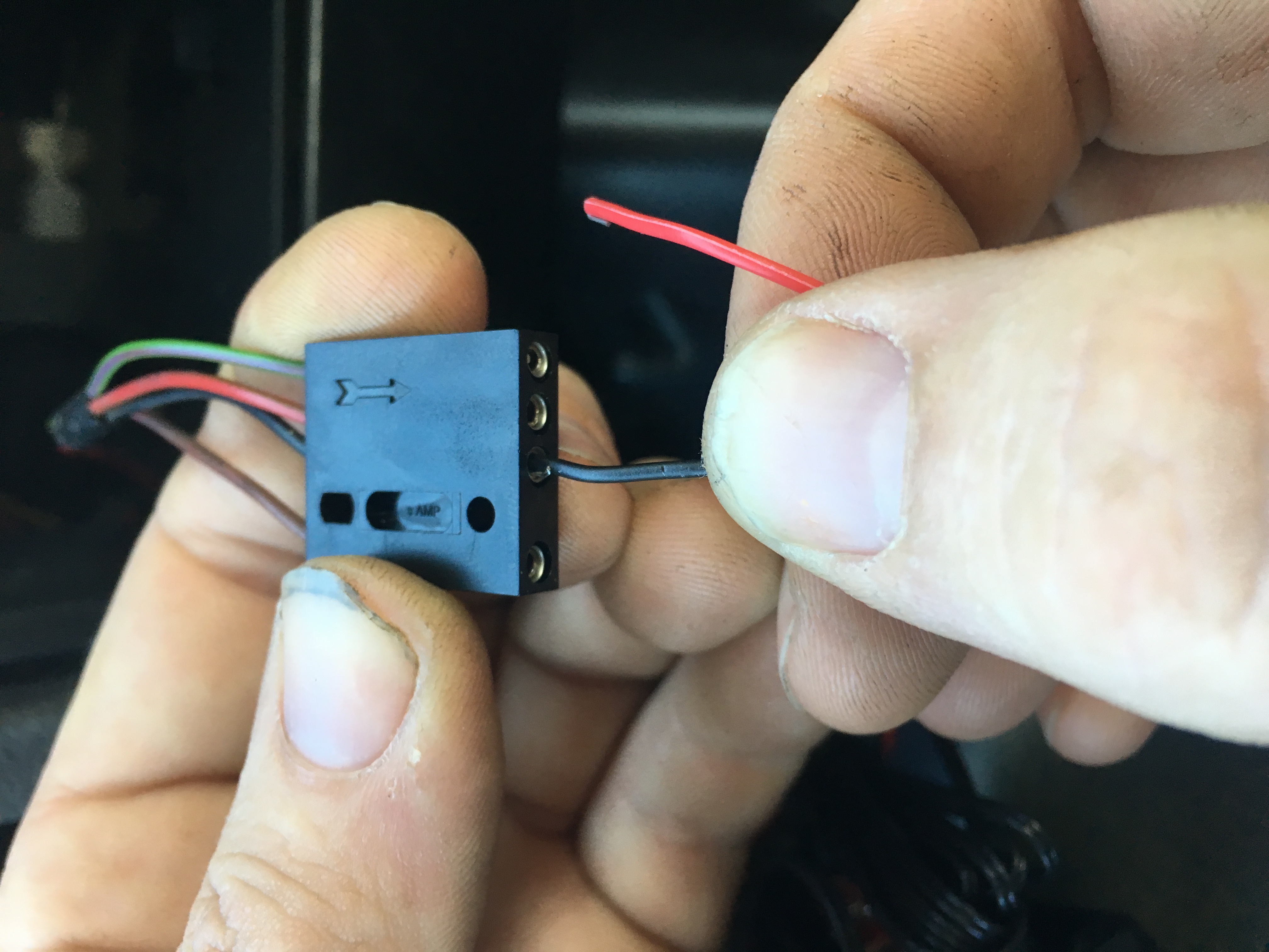
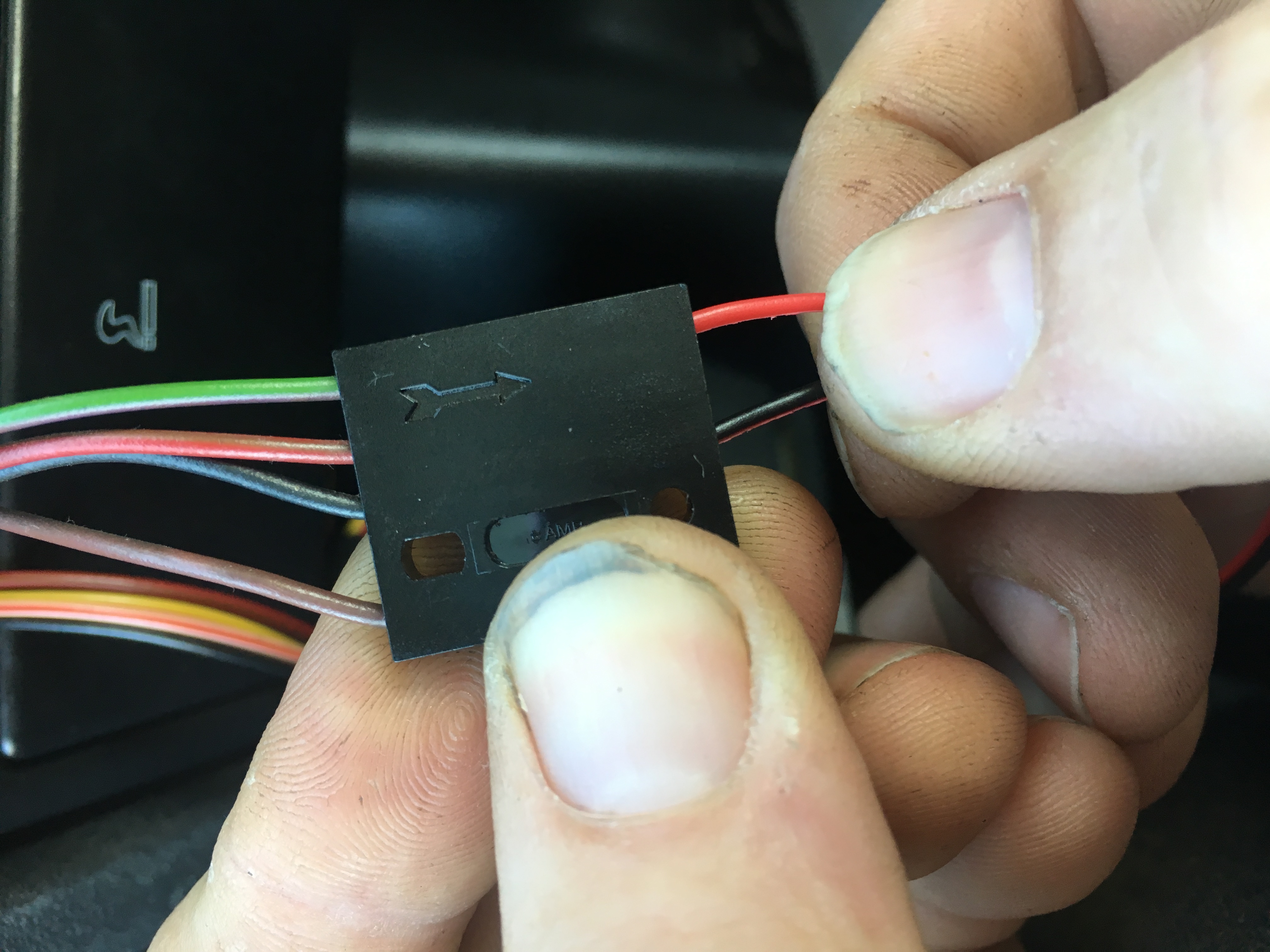
Grab your screwdriver and screw the black wire into the connection block in the position shown. use the twists you just created into the terminal block
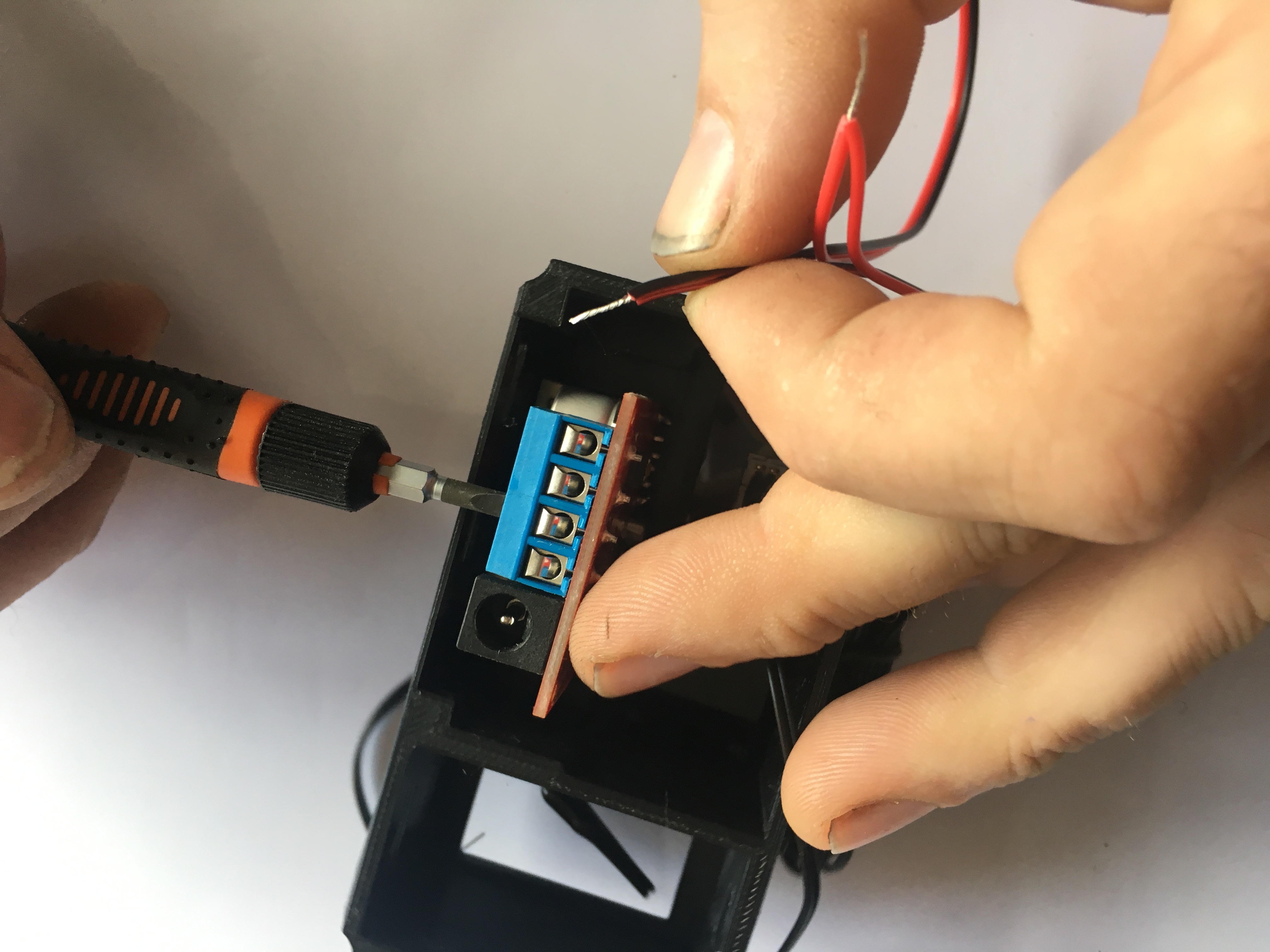
Pay attention to the correct hole for the BLACK wire
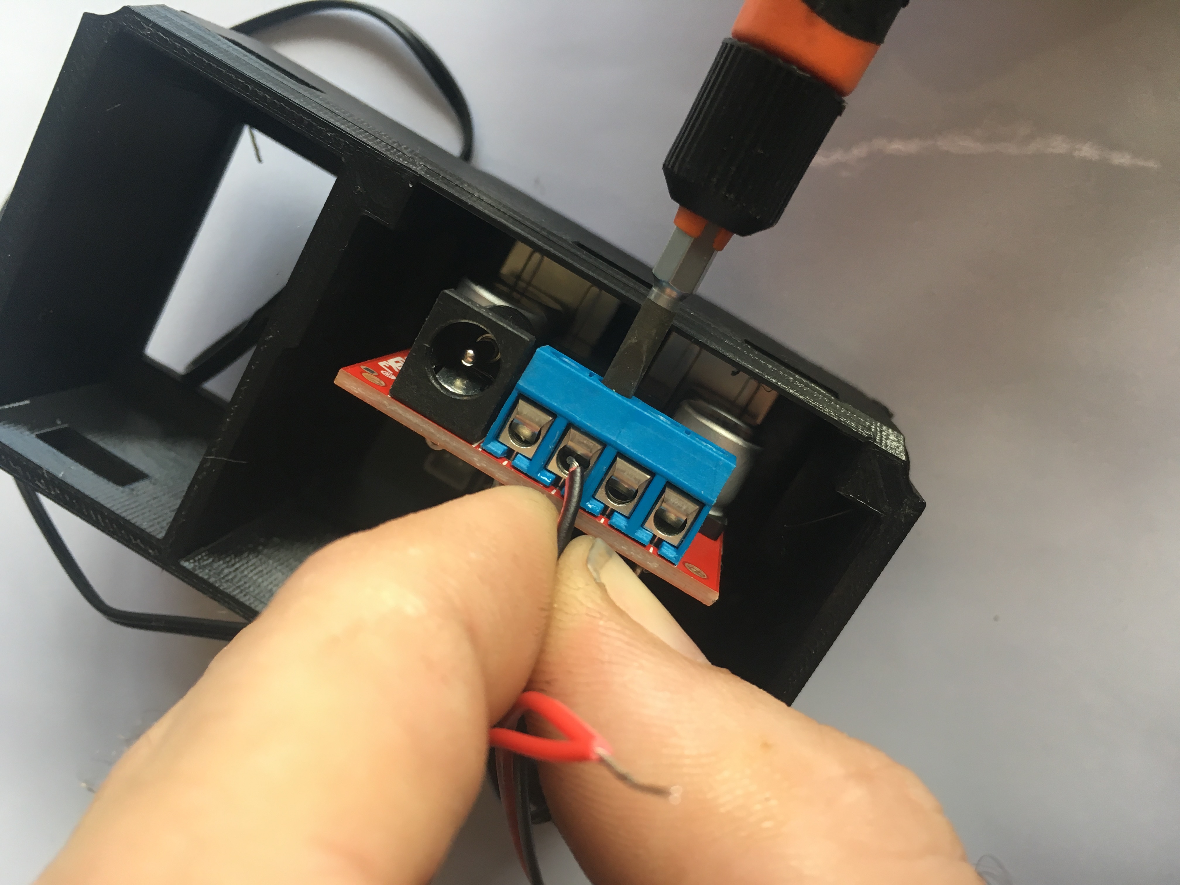
screw the RED wire into the connection block in the position shown. use the twists you just created into the terminal block
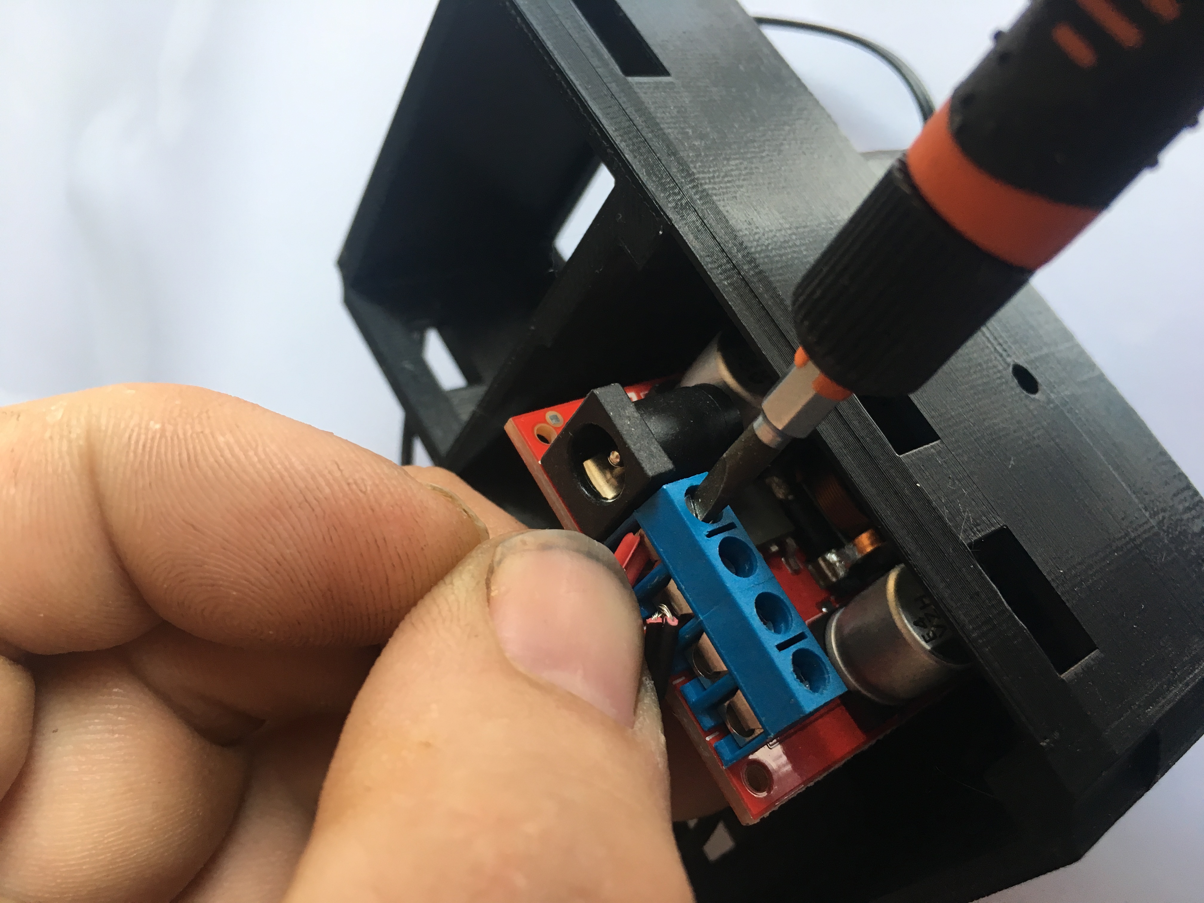
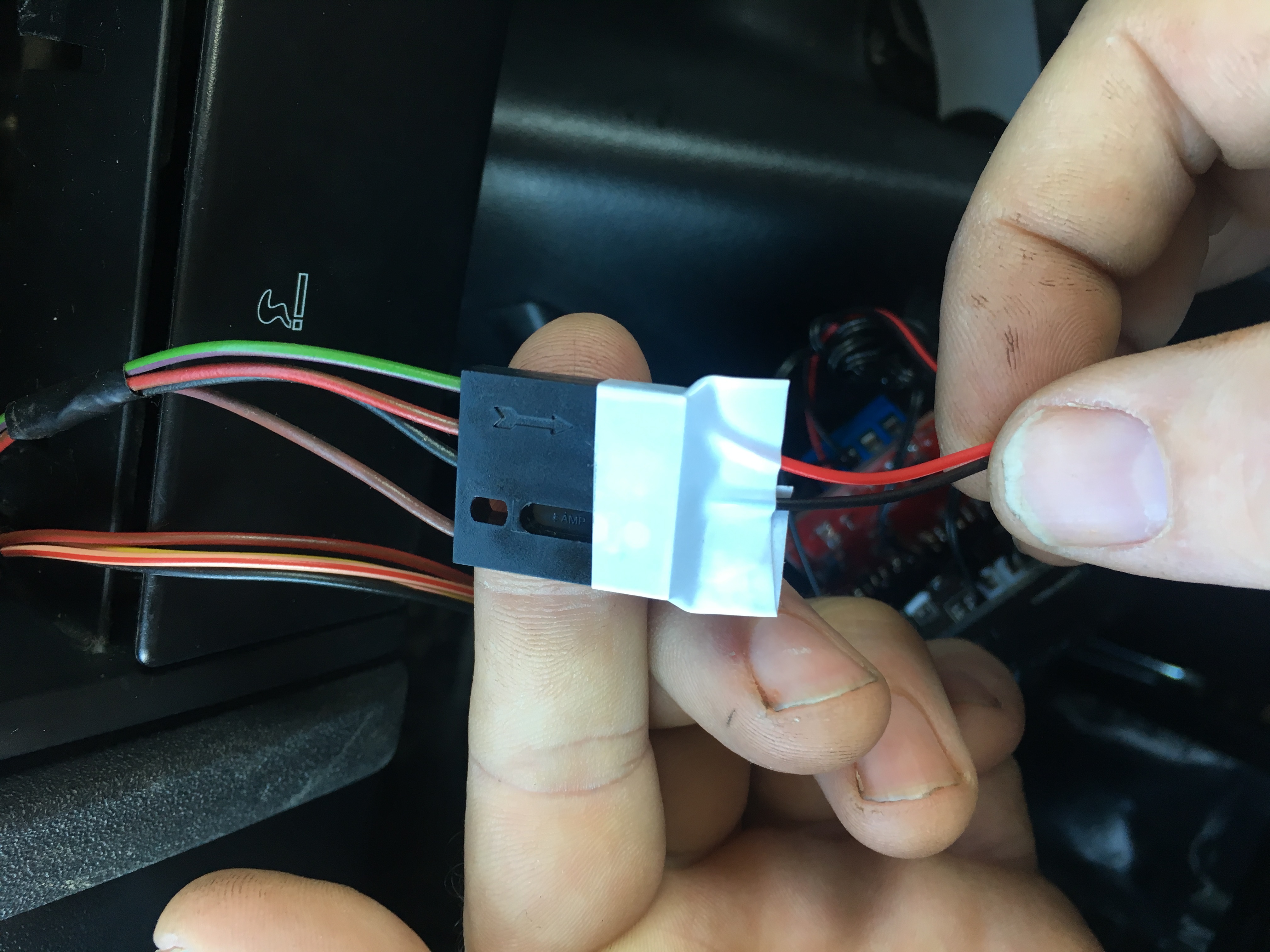
Double check you got the wires in the correct terminals
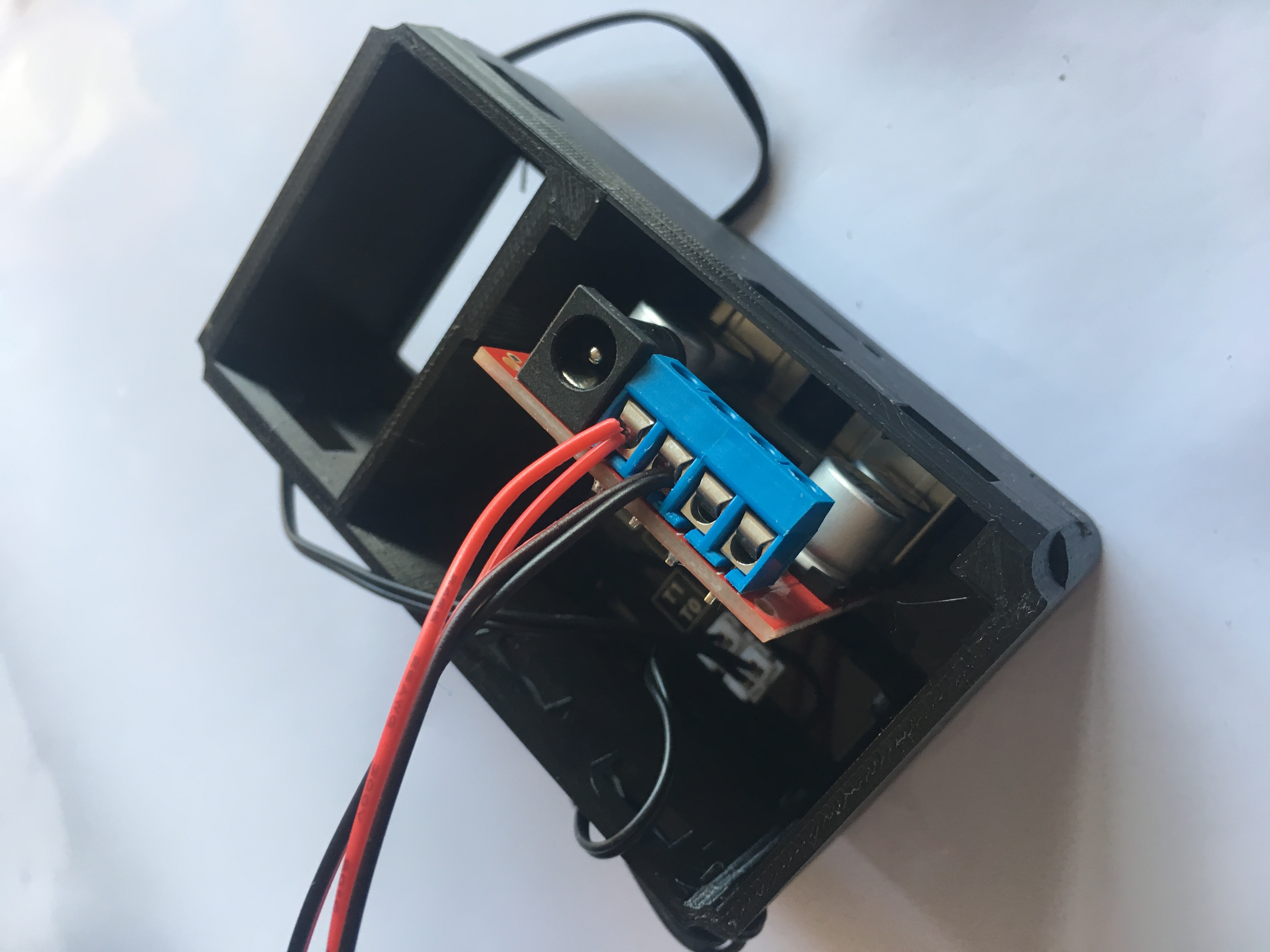
Reconnect the power supply to the clock module, Needle nose pliers may help here
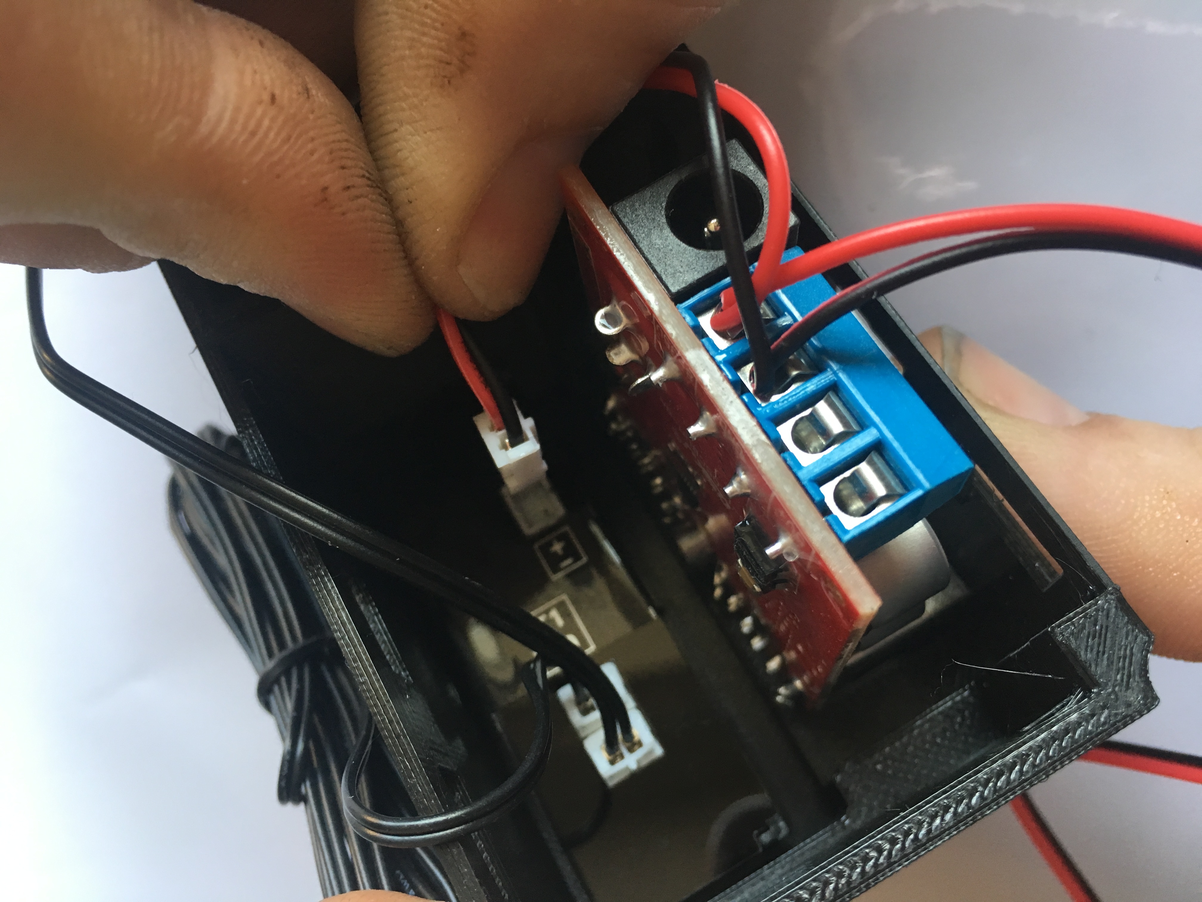
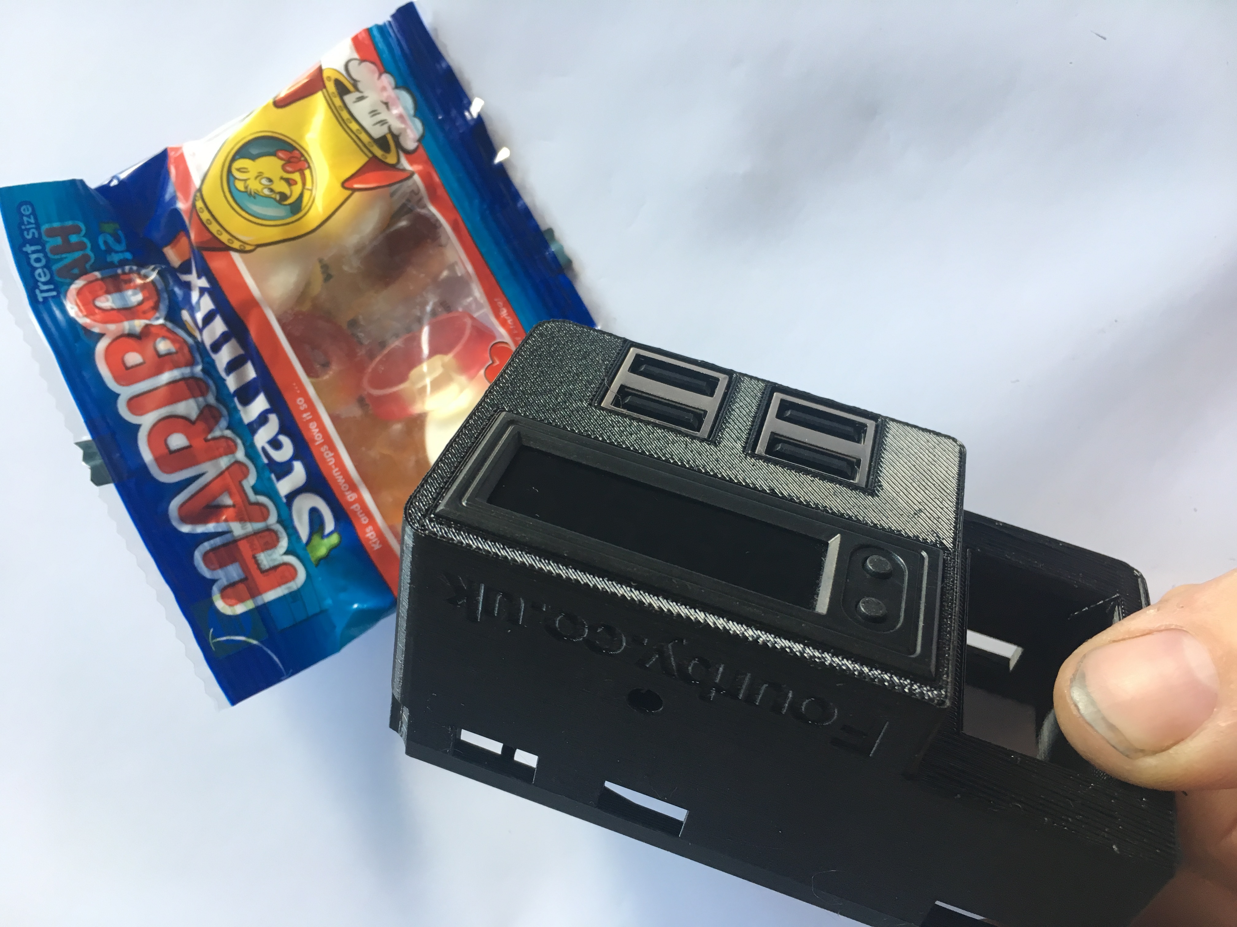
Your clock is built.... Haribo Time...!!!
![]()
Time to go to the car....
******WARNING******
During this install process you will be operating the central locking button of your car, keep your keys on you. you dont want to end up locked out of your car.
Dont let this be you..!!
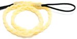
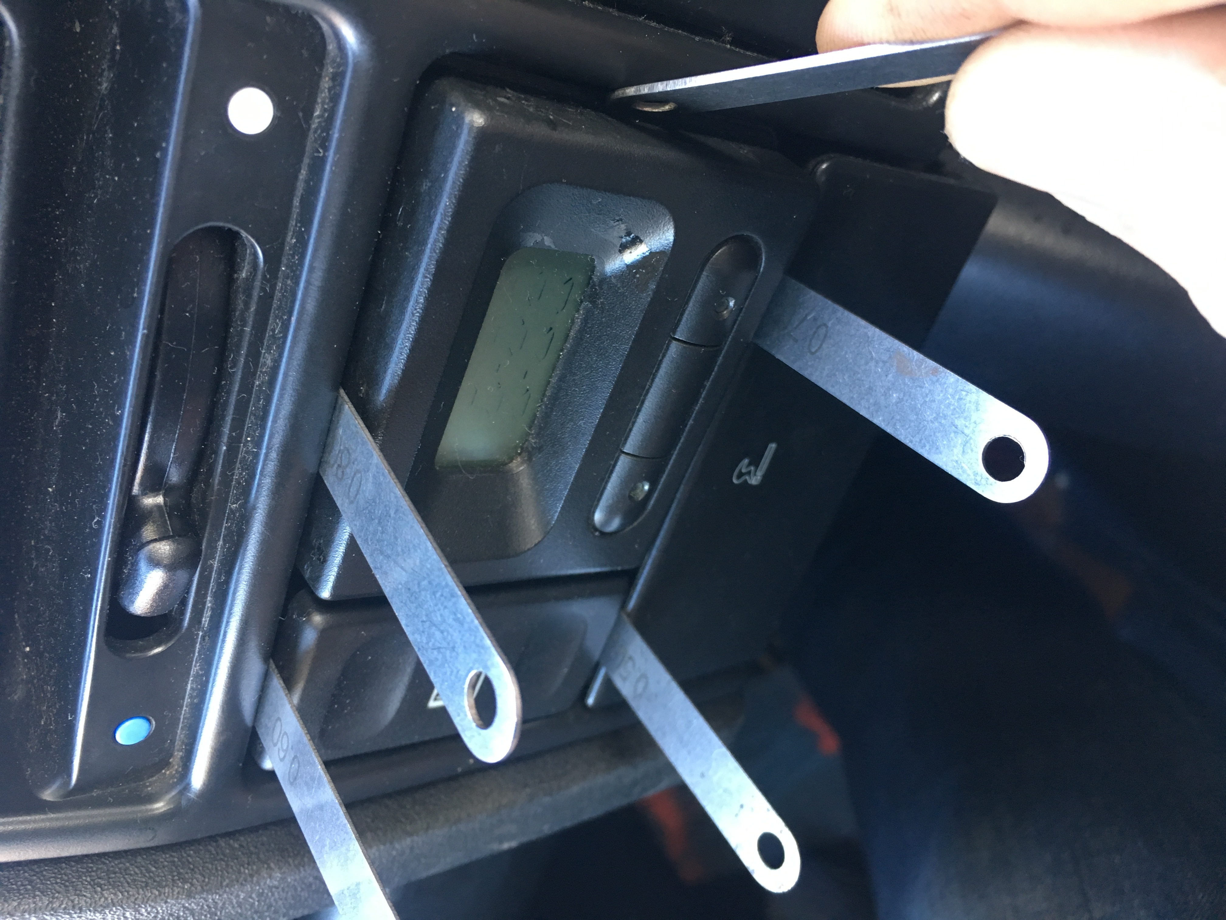
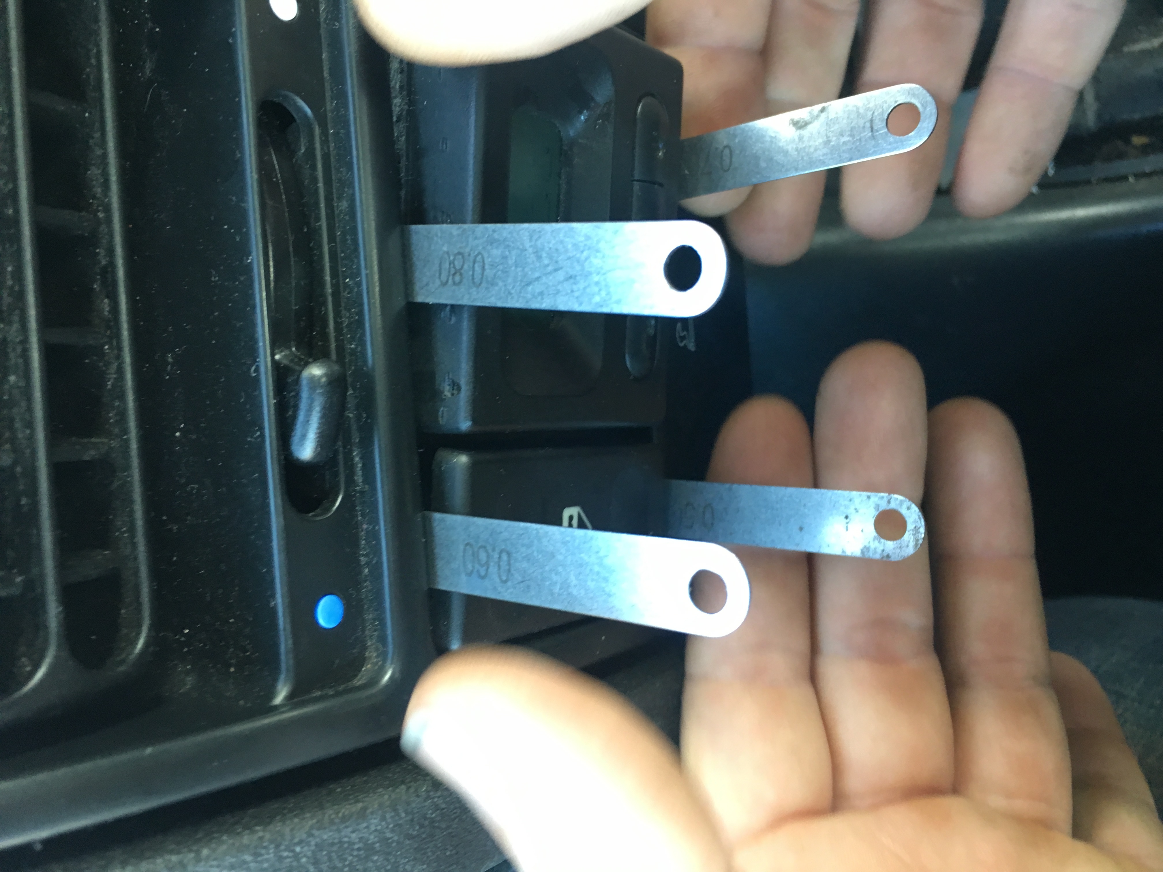
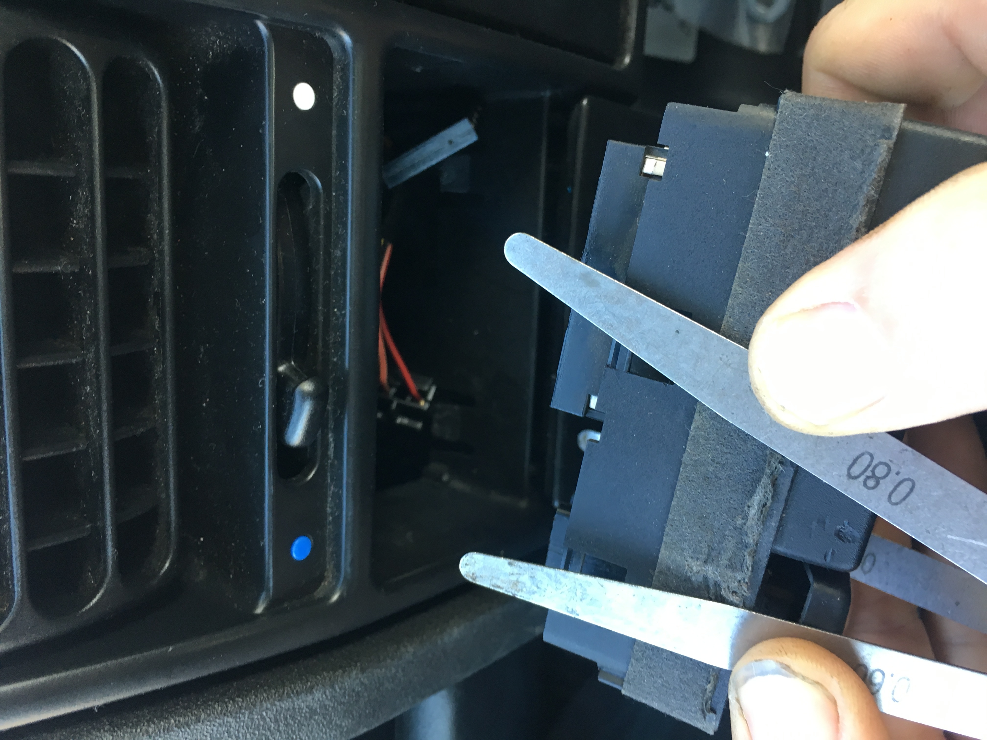
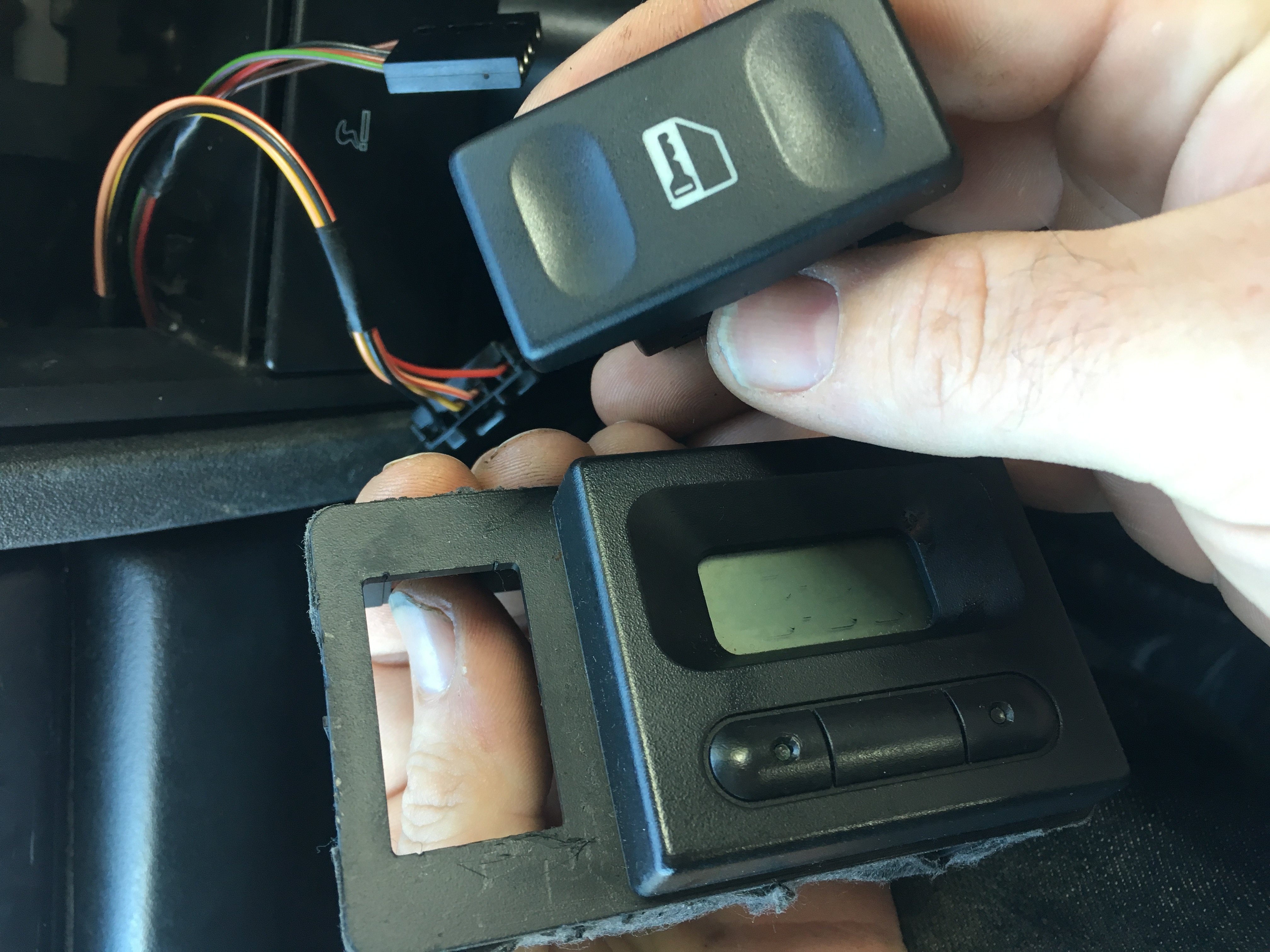
You will need a set of shims to remove the old clock, a set of feeler guages works a treat.
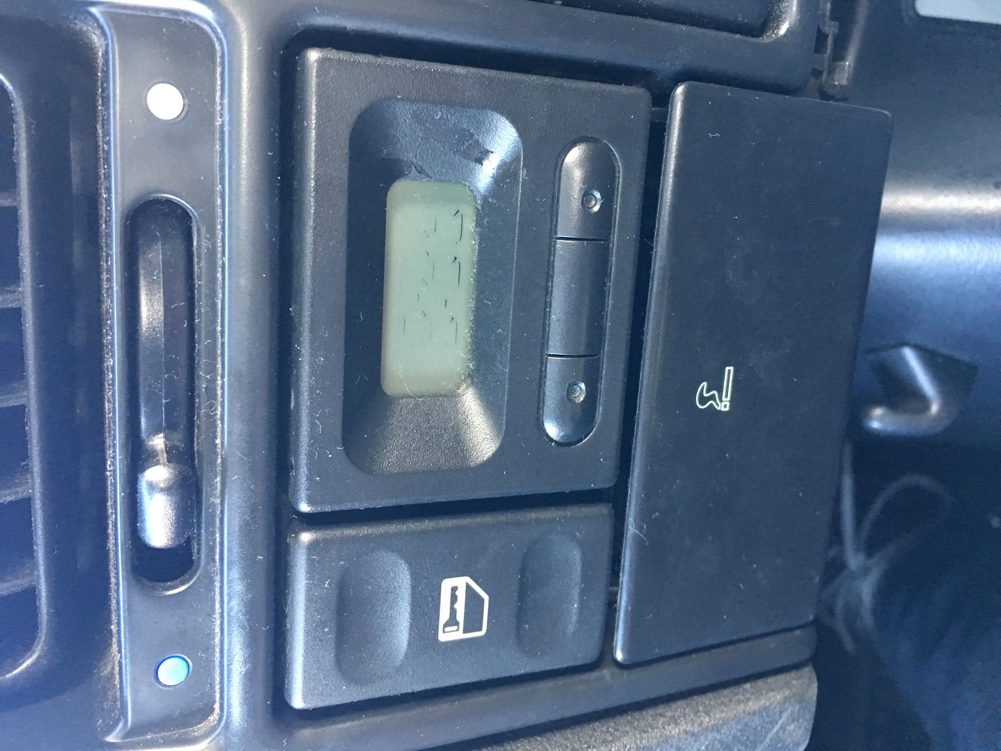
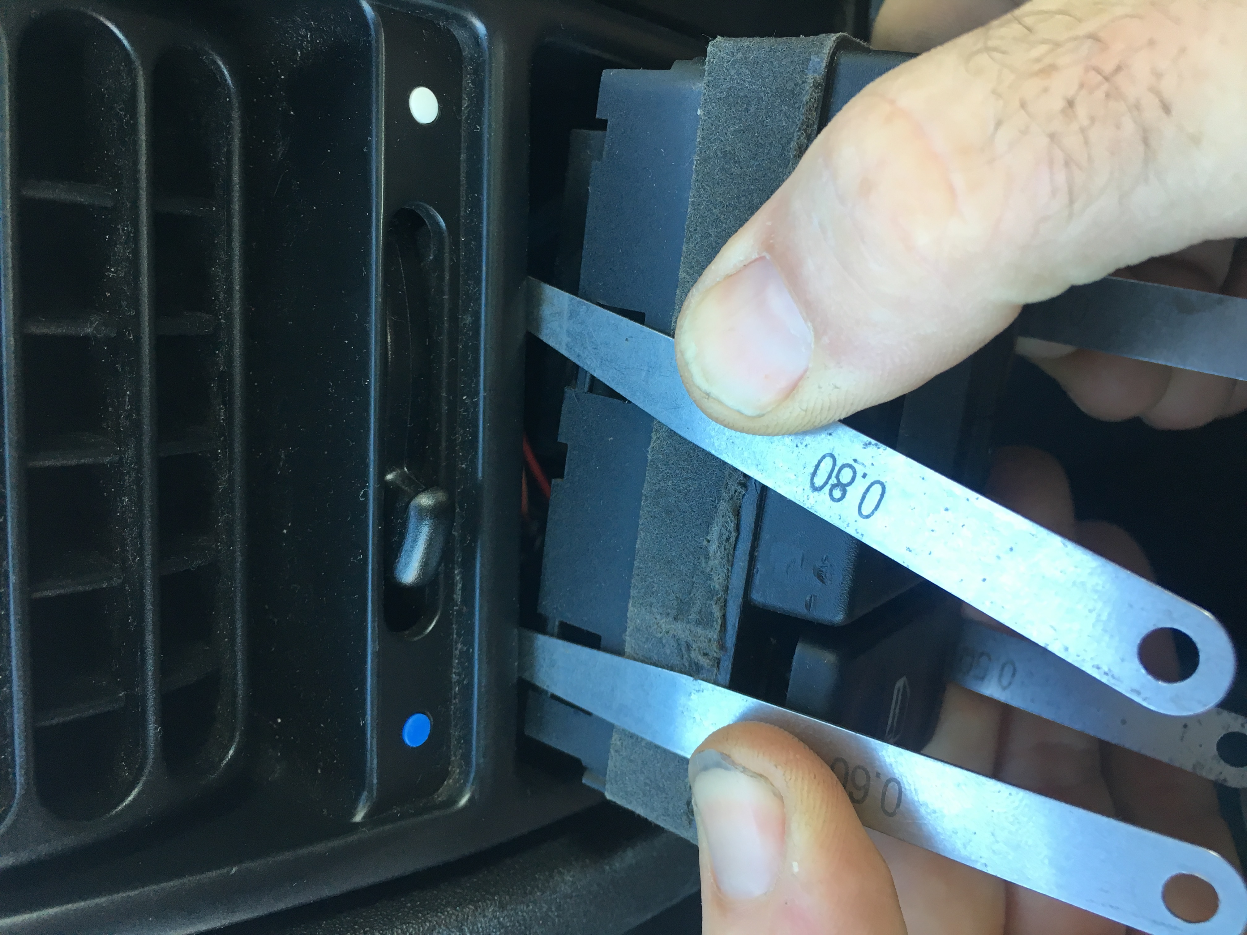
There are 4 clips that hold the original clock in, they need to be pushed back so the old clock can slide out, put your shims in these possitions and have a feel for them, once you locate them you will need to slide the shim between the clock body and the clips moulded into the dash surround, once you get all 4 the clock will come out.
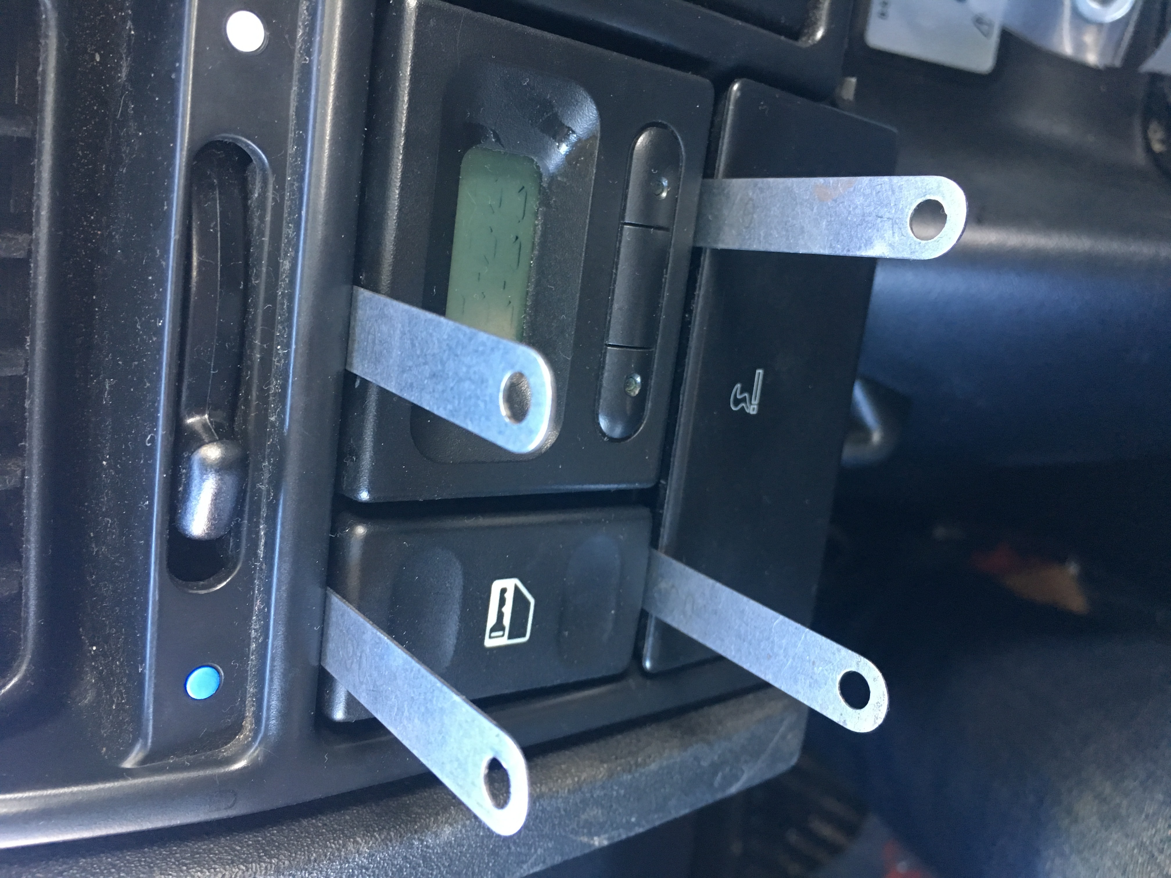
in this photo the clock is removed and you can see the lower 2 clips
once you get all 4 clips the clock will come out
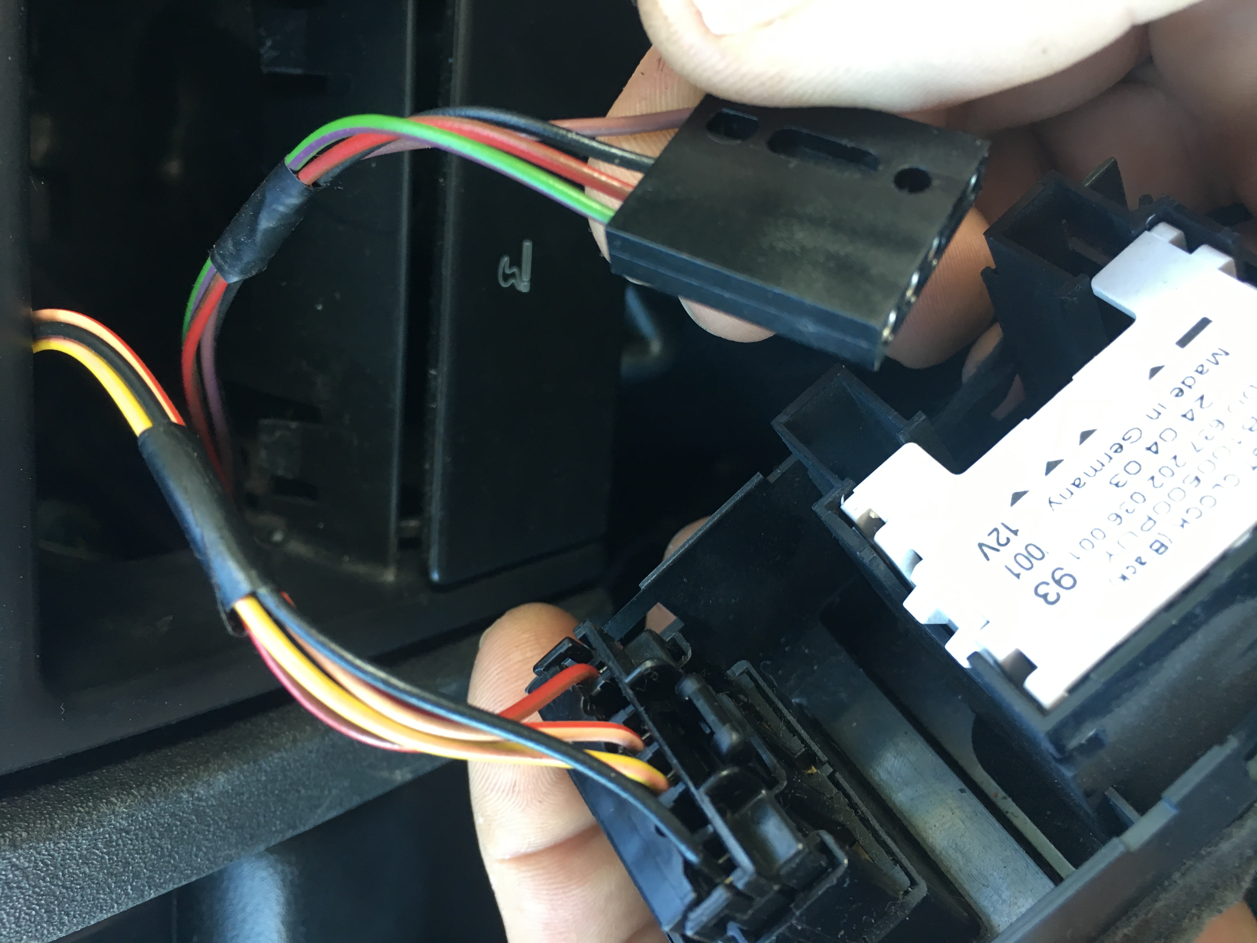
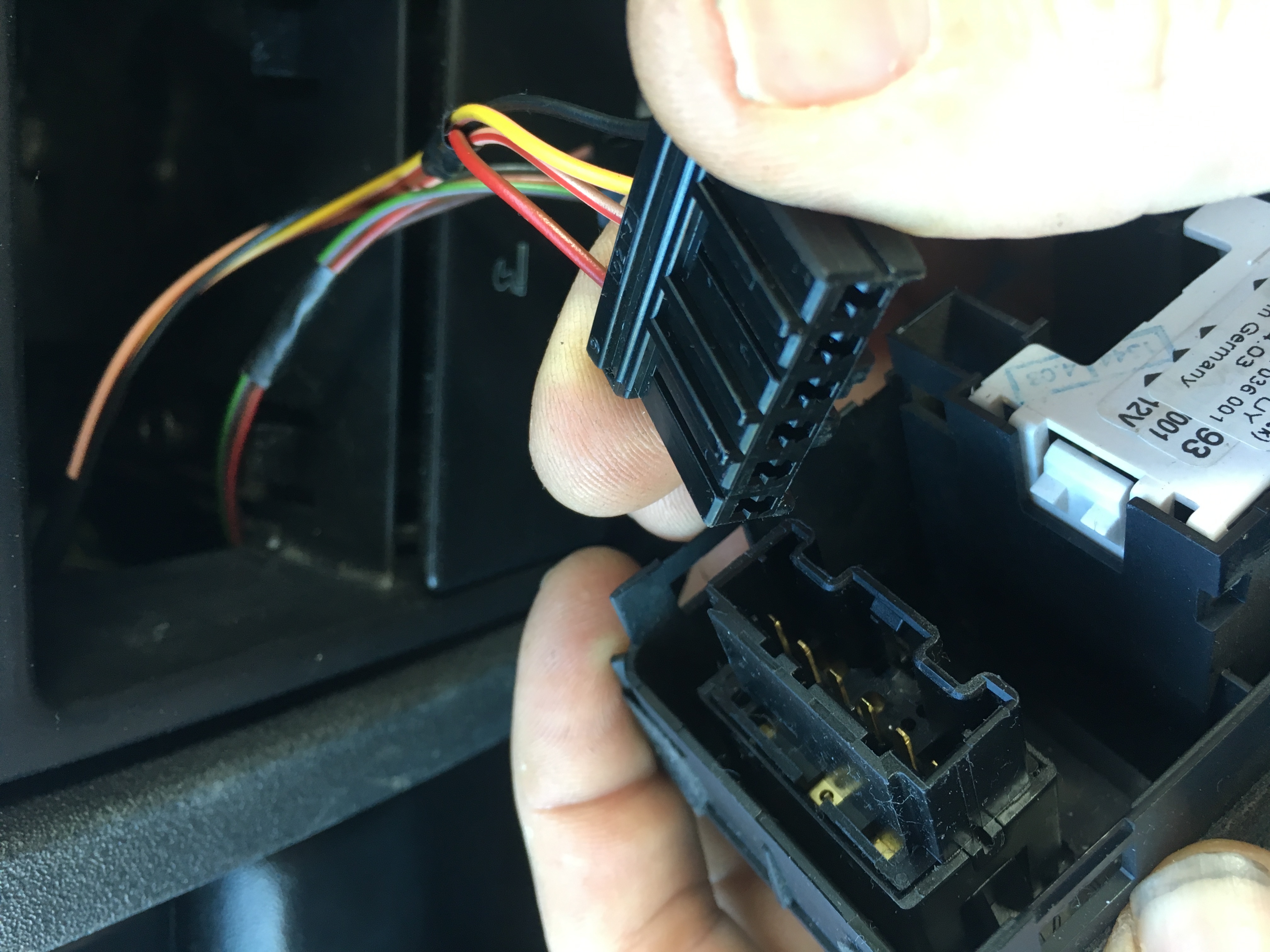
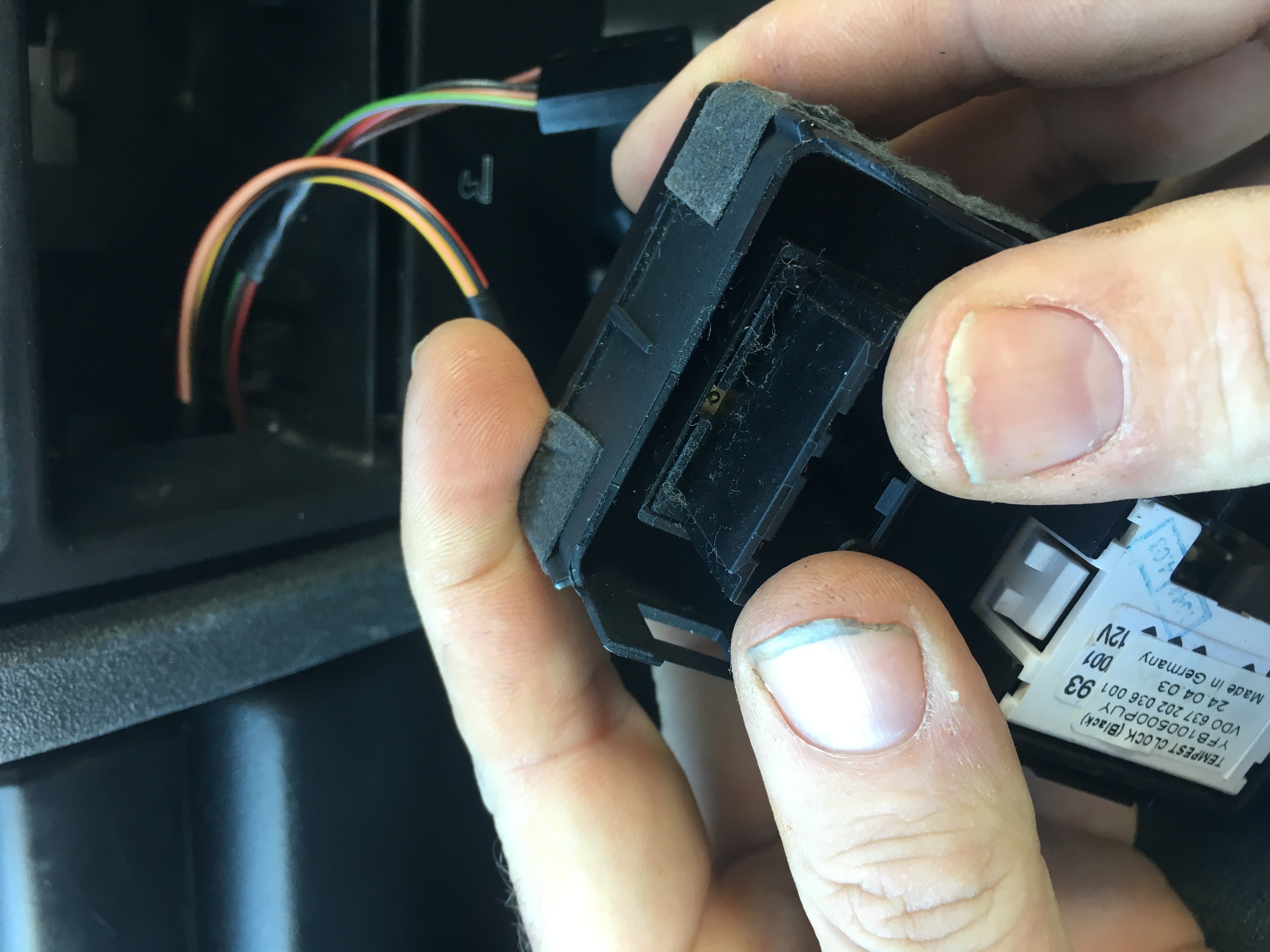
Use tape to secure the wires.
Taping the connector might not be your idea of making a sound connection, we understand that. So use any method you wish to connect the wires, you could cut the cars loom and use crimp connectors or solder, or you could bring the original wiring loom connetors to the screw terminal block on the USB module. This wiring, it's up to you....

Stick this sticker to your door jam

Your Fourby Multifunction USB Clock install is now complete,
Point your phone at the QR code sticker in your door jam, you will program and calibrate the clocks operation....

![]()
Fourby USB Clock Setup, Programming and Calibration
")