Aftermarket 4x4 Parts and Accessories
Expedition & Overland Preparation
Outdoor, Camping & Bushcraft Products


Categories Wiring Guide
Wiring Guide
Clock wiring
Please note:
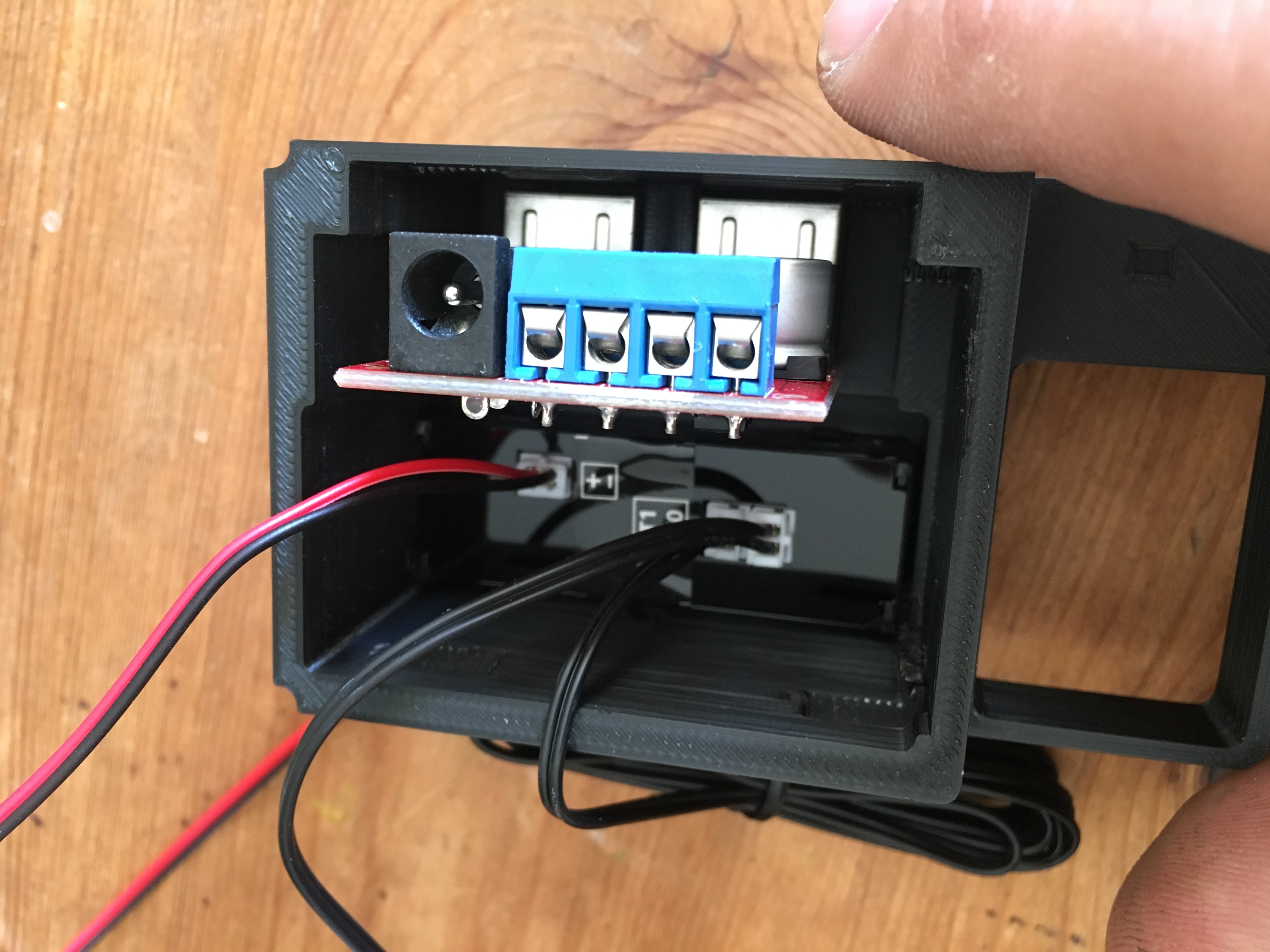
Images displayed below are from a D1 clock build, if you have a D2 clock the process is the same for the electronics.
You will need to supply power to both the clock module and the USB module.
We will do that by using the wire that came with the clock and jumpering it into the USB module.
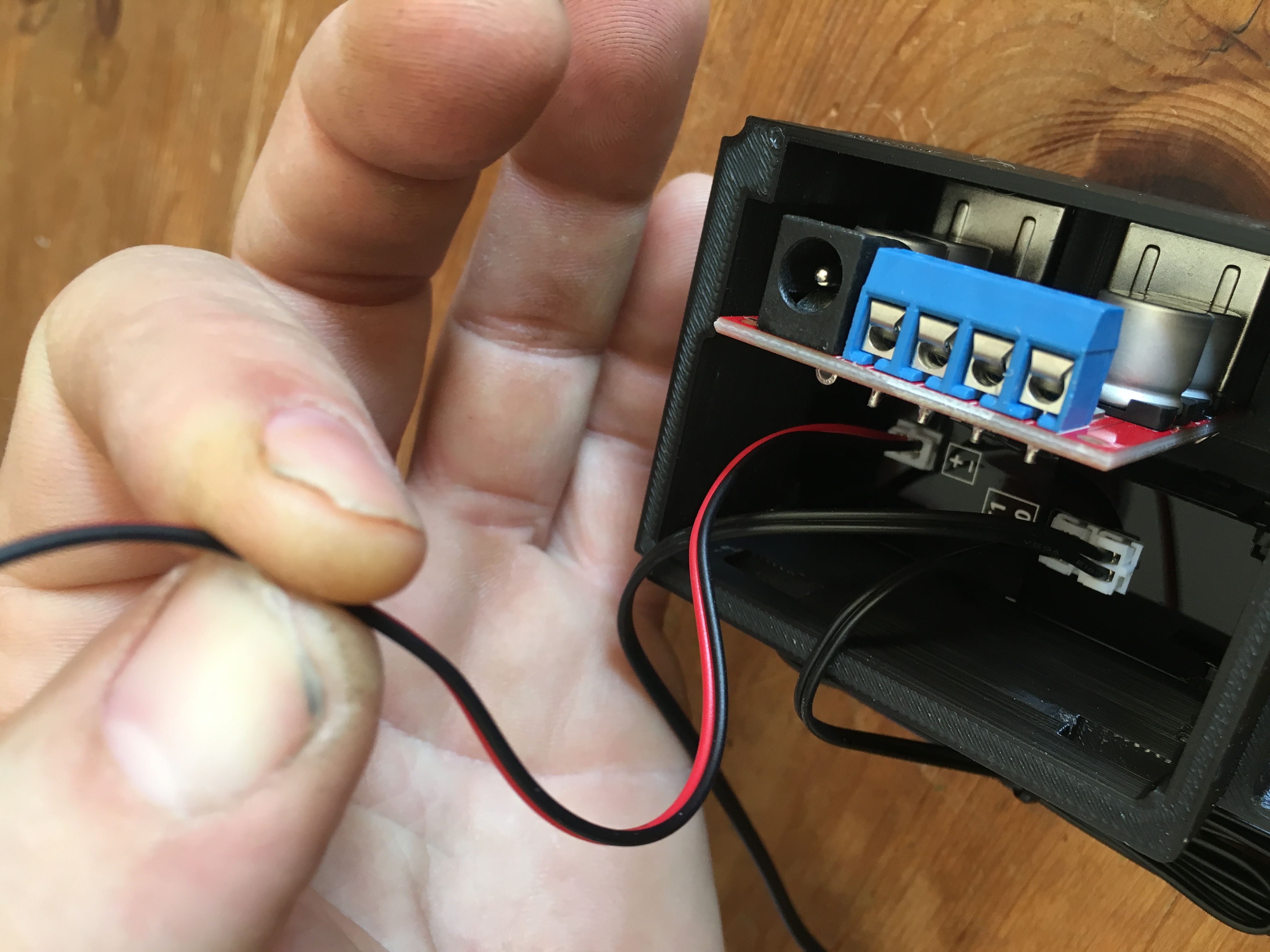
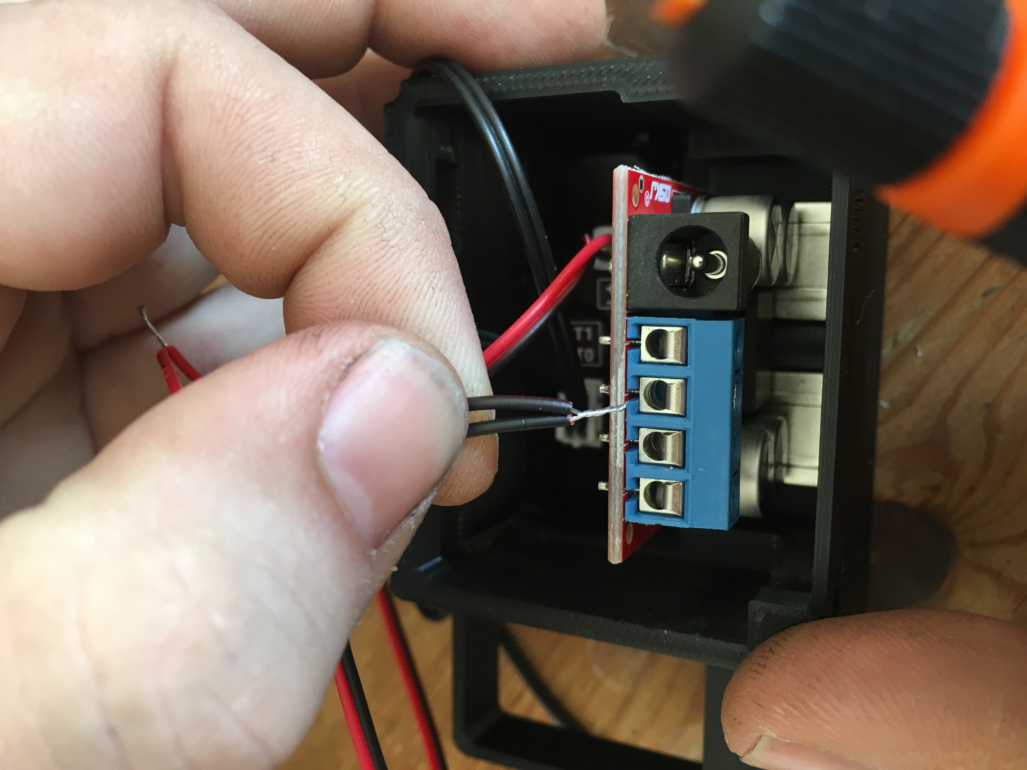
locate enough wire from the clock module to feed into the blue connector of the USB
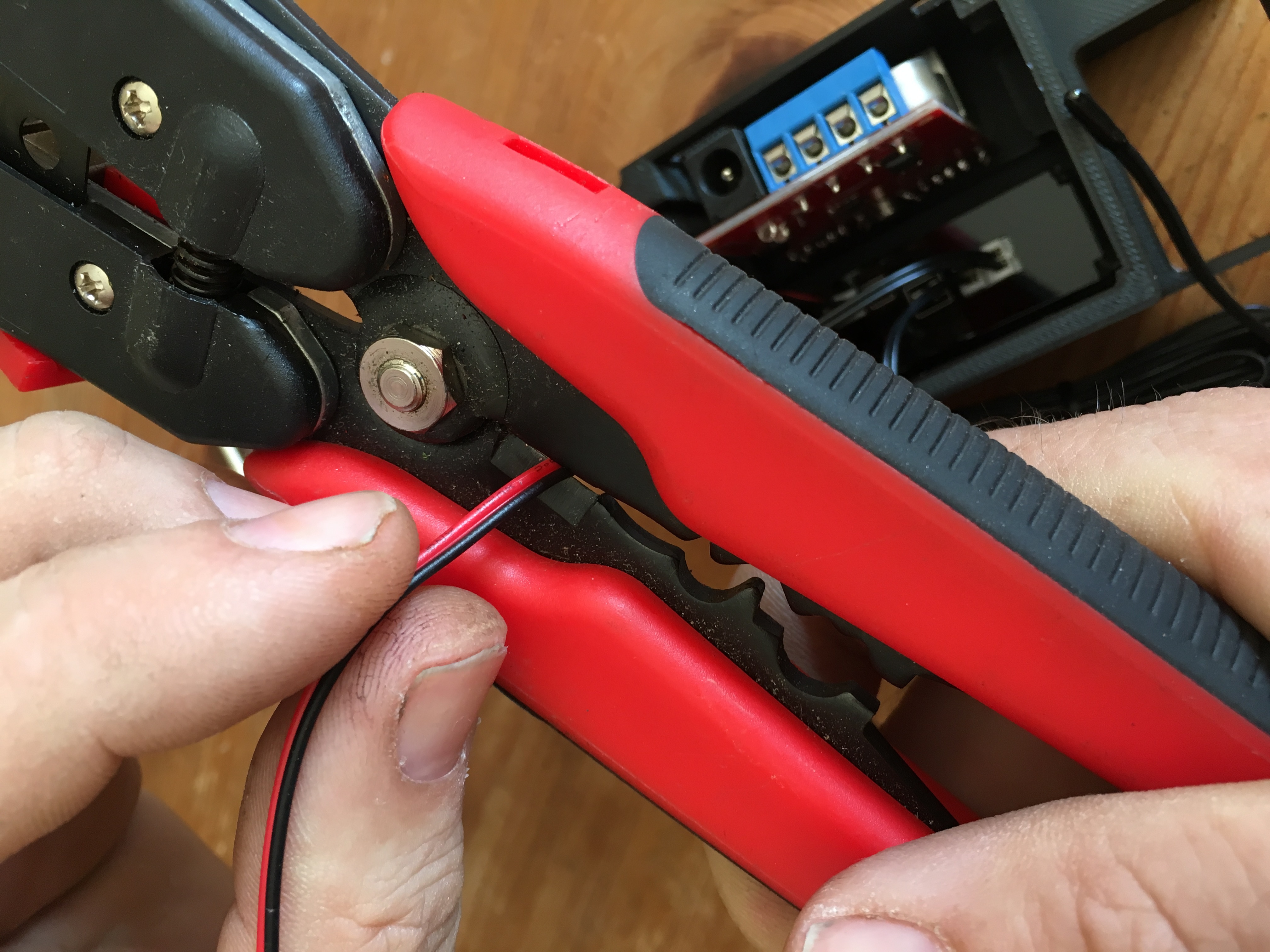
Cut the wire and strip the insulation back
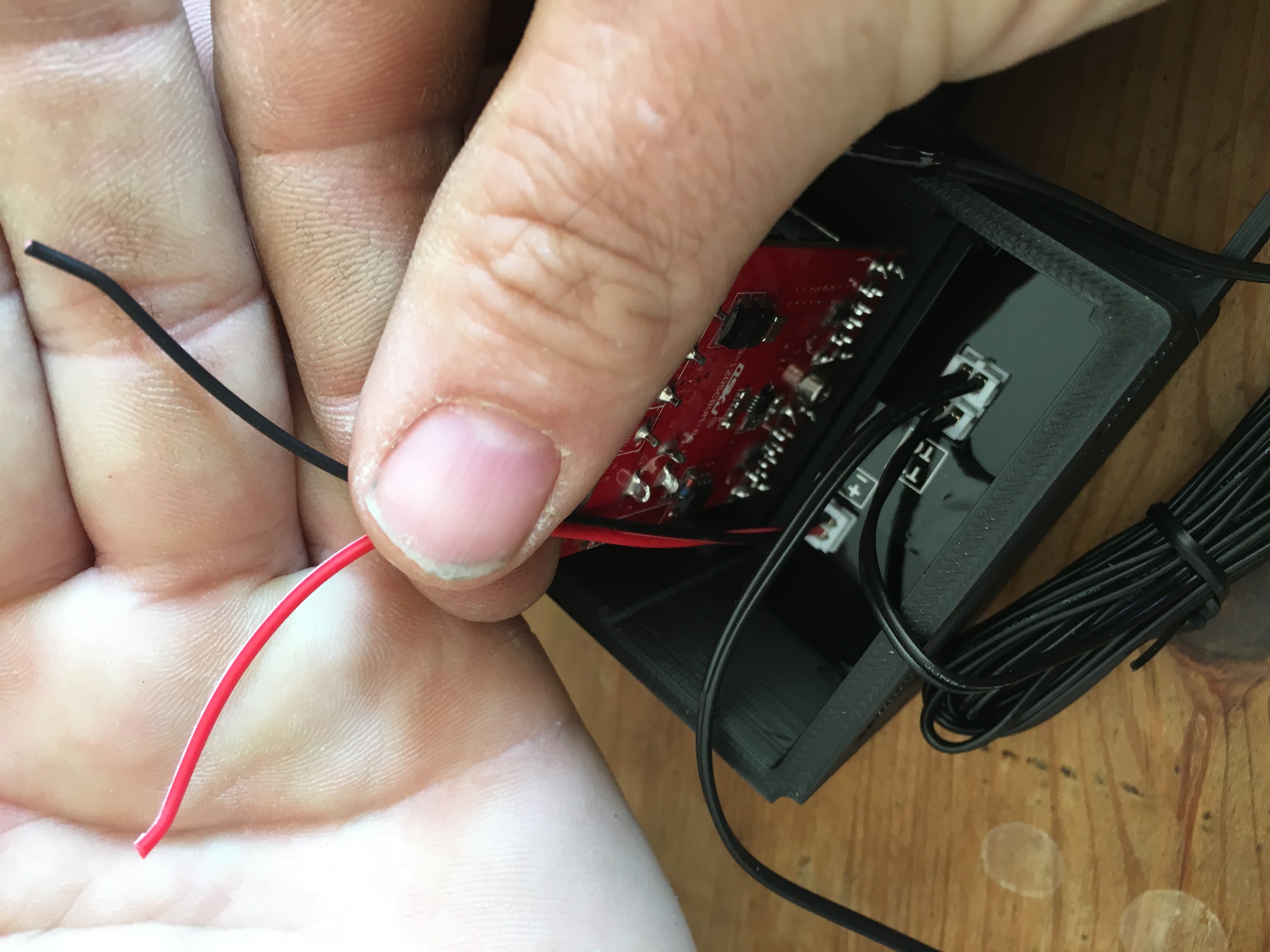
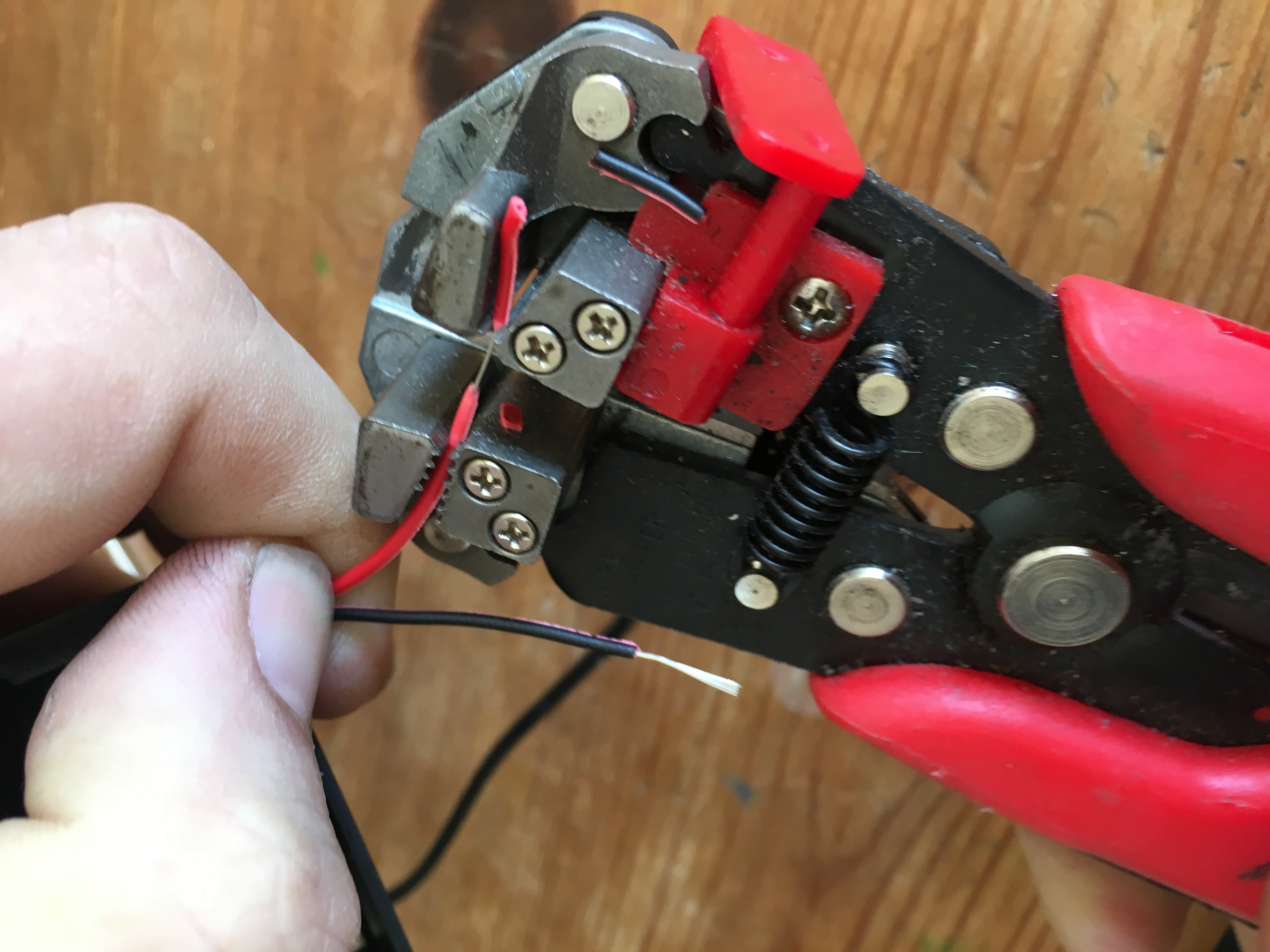
Strip the insulation from the end of the wire that you cut off
twist the two wires back together, paying attention to match the colours of the insulation.
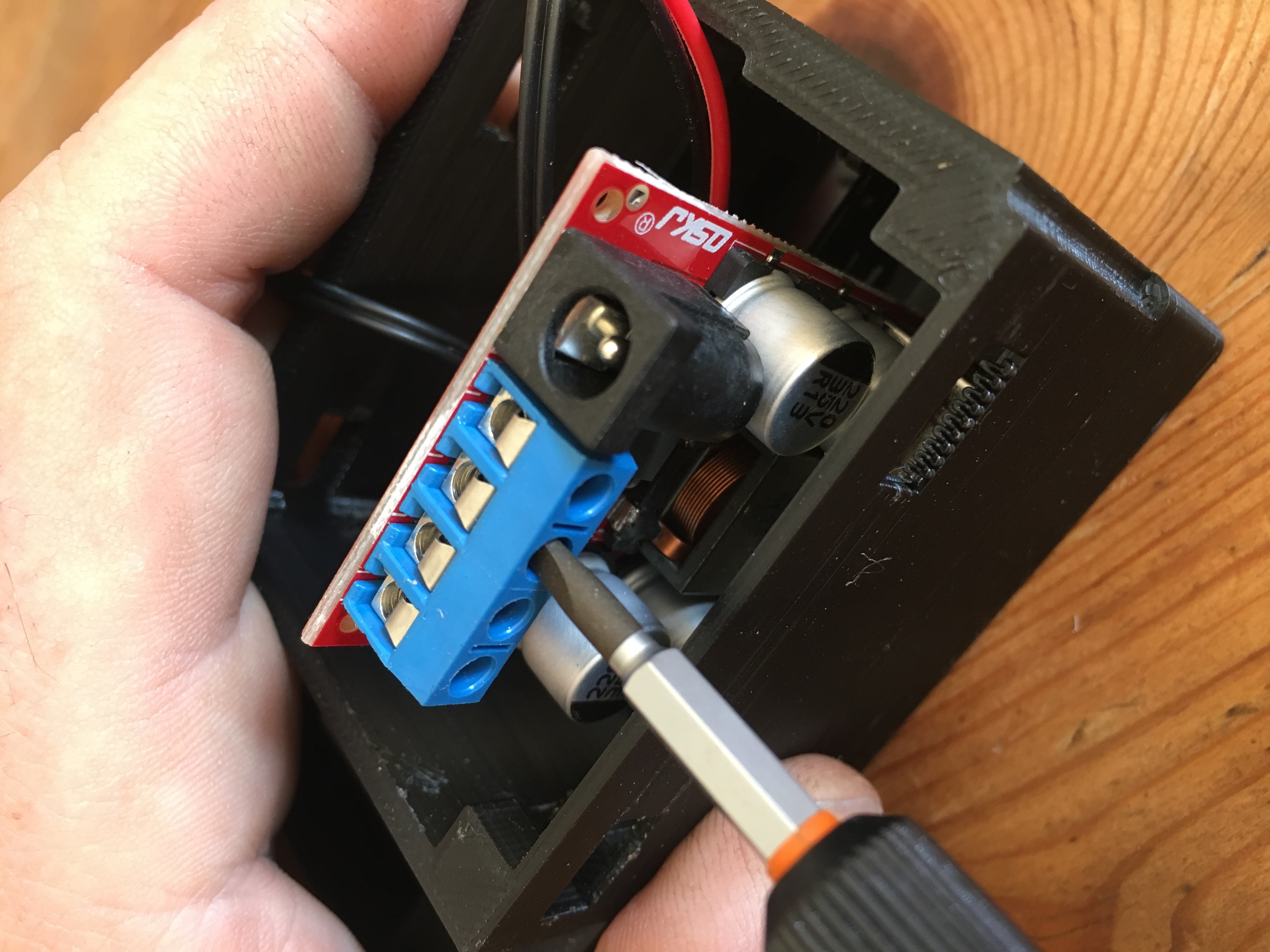
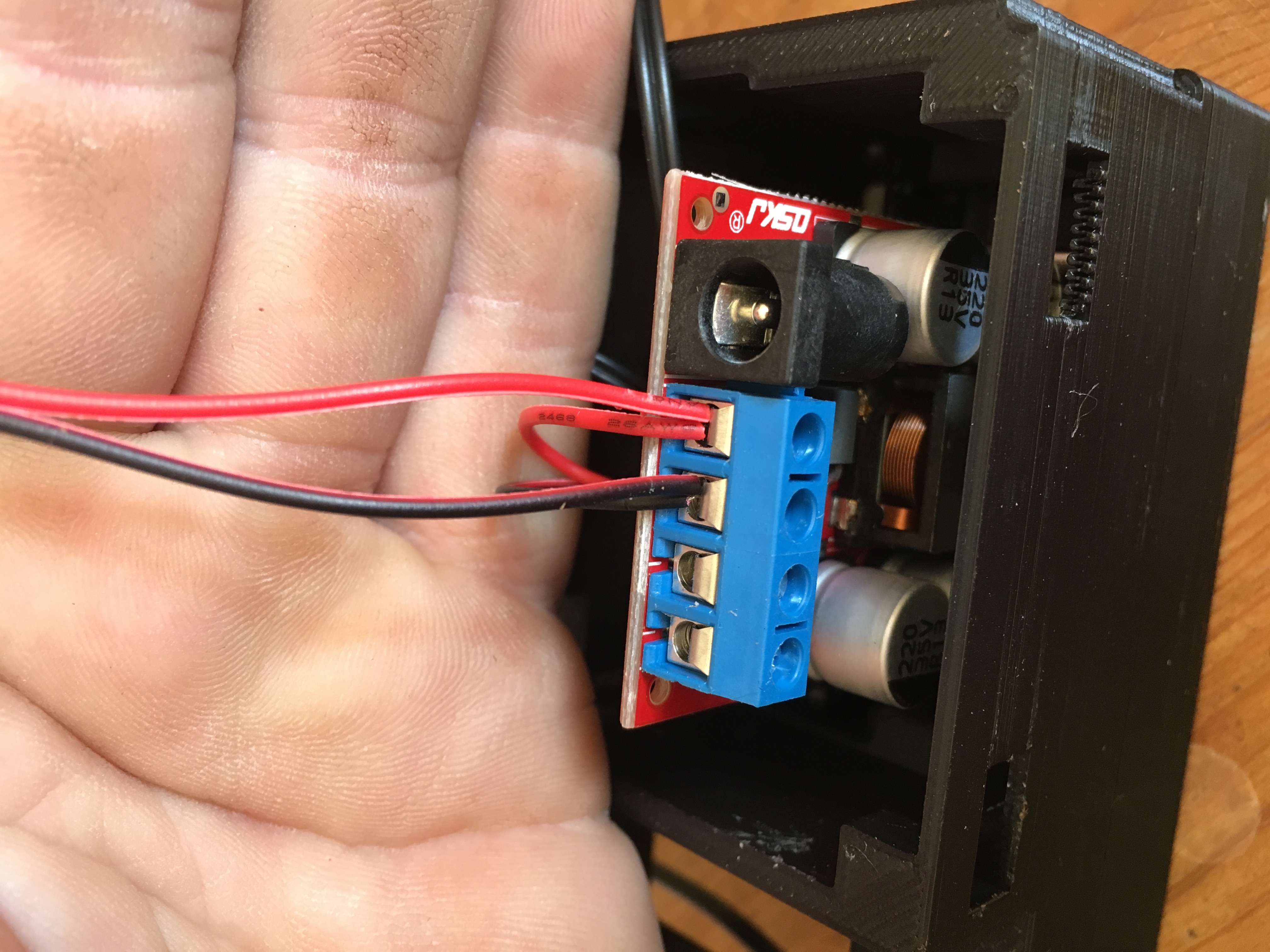
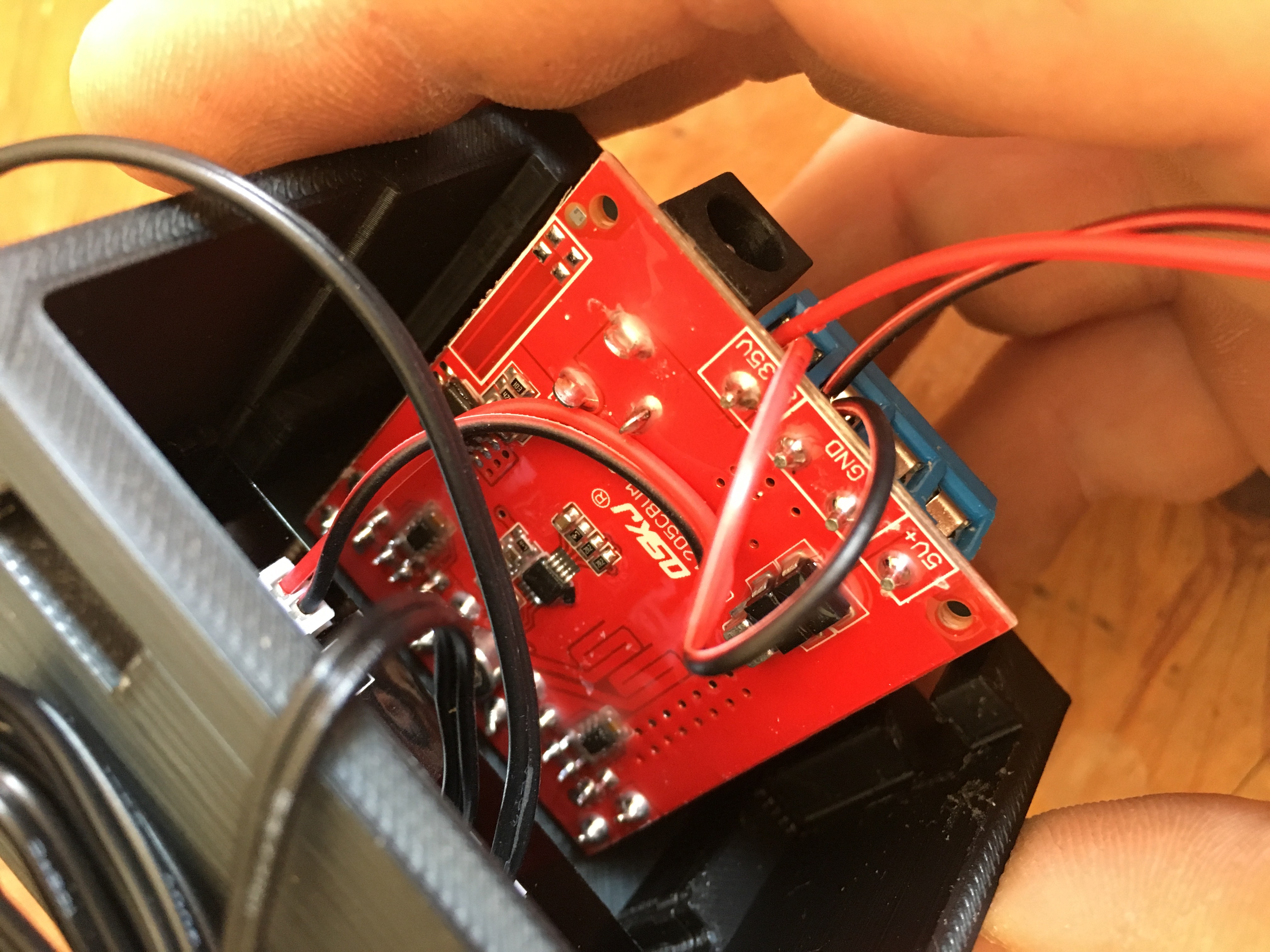
Observe the Polarity markings on the USB board.
Use a small screwdriver to open screw on the blue connector
Attach the Black/Ground Wire to the center connector, (the end of the wire that is the two ends you twisted together.)
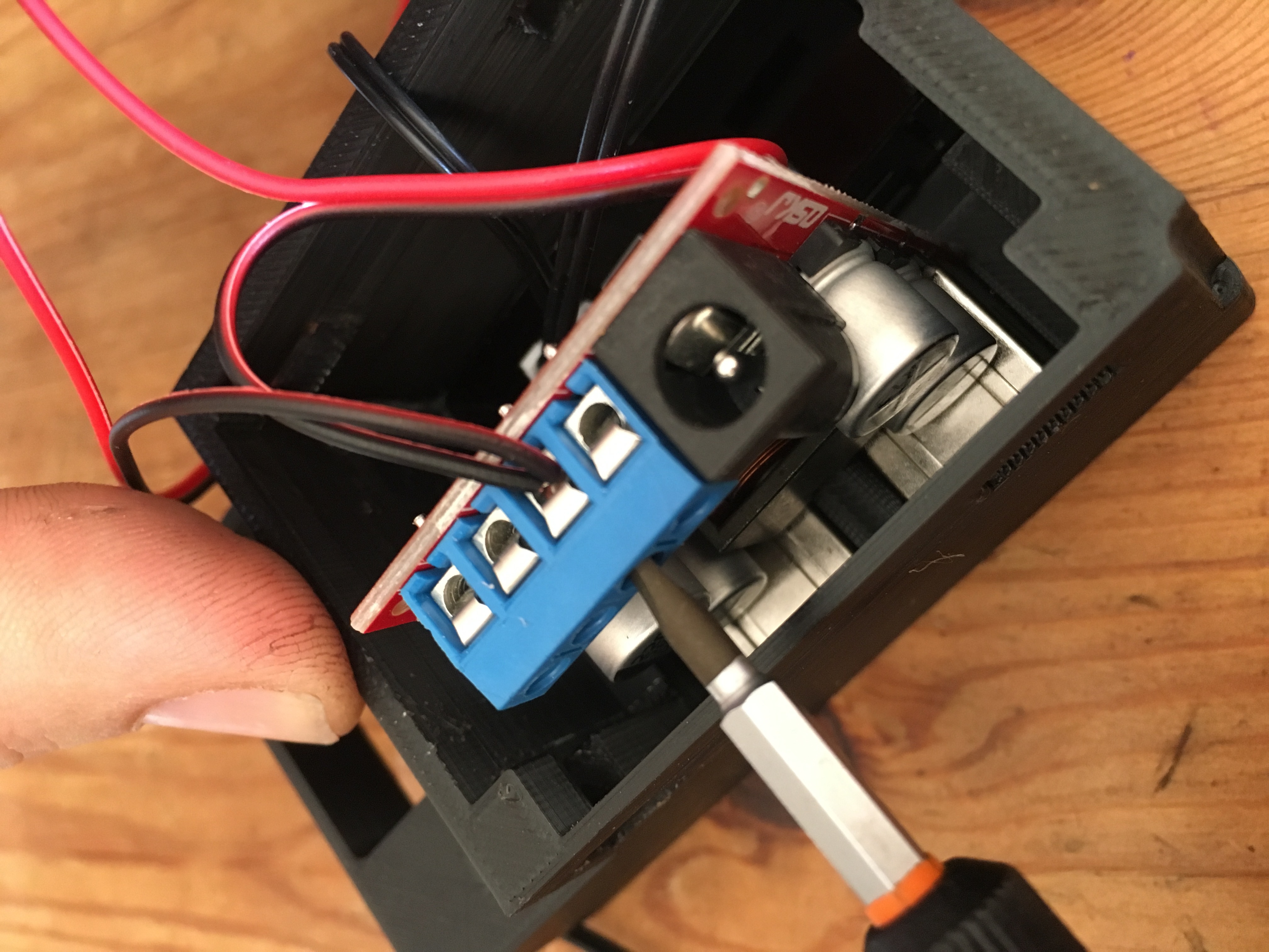
Attach the RED/Live Wire to the outer connector nearest the Jack Plug (the end of the wire that is the two ends you twisted together.)
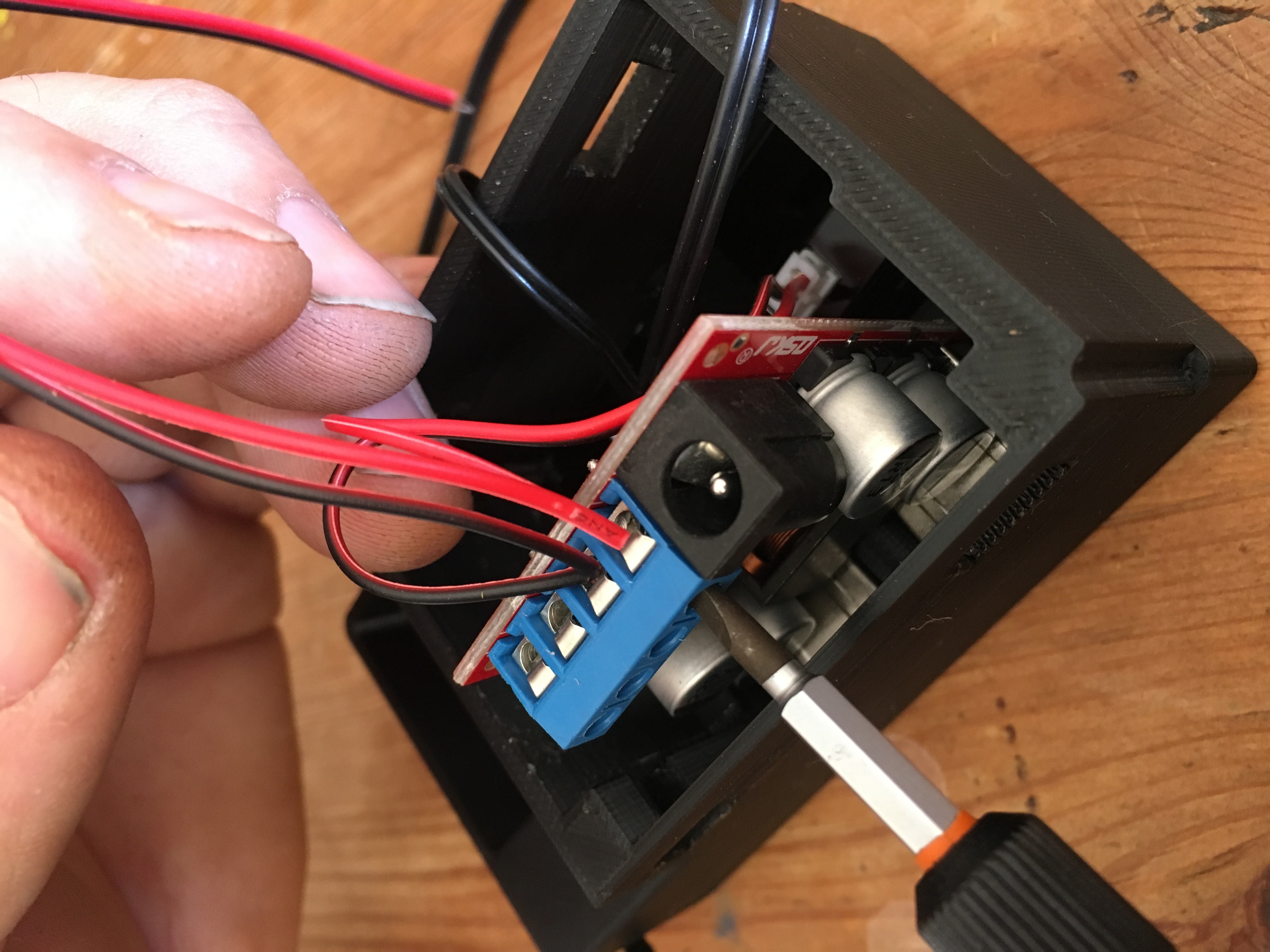
Your clock should now be jumpered off the USB module using the same wiring.
Your Fourby clock build is now complete, you are ready to install it into the car.
Click either for Discovery 1 (300tdi)
Or Discovery 2 (TD5/V8)
Discovery 1
or
Discovery 2
")